Dodge Dakota (R1). Manual - part 365


  Index      Dodge     Dodge Dakota (R1) - service repair manual 2000 year


Search            


Content   ..  363  364  365  366   ..


Dodge Dakota (R1). Manual - part 365


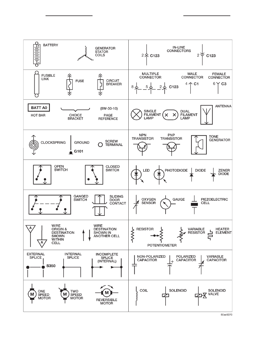
Fig. 3 WIRING DIAGRAM SYMBOLS

8Wa - 01 - 4

8W-01 WIRING DIAGRAM INFORMATION

R1

WIRING DIAGRAM INFORMATION (Continued)

TERMINOLOGY

This is a list of terms and definitions used in the

wiring diagrams.

LHD . . . . . . . . . . . . . . . . . Left Hand Drive Vehicles
RHD . . . . . . . . . . . . . . . . Right Hand Drive Vehicles
ATX . . Automatic Transmissions-Front Wheel Drive
MTX . . . . Manual Transmissions-Front Wheel Drive
AT . . . . Automatic Transmissions-Rear Wheel Drive
MT . . . . . Manual Transmissions-Rear Wheel Drive
SOHC . . . . . . . . . . . Single Over Head Cam Engine
DOHC . . . . . . . . . . Double Over Head Cam Engine
Built-Up-Export . . . . . . . . Vehicles Built For Sale In

Markets Other Than North America

Except-Built-Up-Export . . Vehicles Built For Sale In

North America

WARNINGS - GENERAL

WARNINGS provide information to prevent per-

sonal injury and vehicle damage. Below is a list of
general warnings that should be followed any time a
vehicle is being serviced.

WARNING:: ALWAYS WEAR SAFETY GLASSES FOR
EYE PROTECTION.

WARNING: USE SAFETY STANDS ANYTIME A PRO-
CEDURE REQUIRES BEING UNDER A VEHICLE.

WARNING: BE SURE THAT THE IGNITION SWITCH
ALWAYS IS IN THE OFF POSITION, UNLESS THE
PROCEDURE REQUIRES IT TO BE ON.

WARNING:

SET

THE

PARKING

BRAKE

WHEN

WORKING

ON

ANY

VEHICLE.

AN

AUTOMATIC

TRANSMISSION SHOULD BE IN PARK. A MANUAL
TRANSMISSION SHOULD BE IN NEUTRAL.

WARNING: OPERATE THE ENGINE ONLY IN A
WELL-VENTILATED AREA.

WARNING: KEEP AWAY FROM MOVING PARTS
WHEN THE ENGINE IS RUNNING, ESPECIALLY THE
FAN AND BELTS.

WARNING: TO PREVENT SERIOUS BURNS, AVOID
CONTACT WITH HOT PARTS SUCH AS THE RADIA-

TOR, EXHAUST MANIFOLD(S), TAIL PIPE, CATA-
LYTIC CONVERTER AND MUFFLER.

WARNING: DO NOT ALLOW FLAME OR SPARKS
NEAR

THE

BATTERY.

GASES

ARE

ALWAYS

PRESENT IN AND AROUND THE BATTERY.

WARNING: ALWAYS REMOVE RINGS, WATCHES,
LOOSE HANGING JEWELRY AND LOOSE CLOTH-
ING.

DIAGNOSIS AND TESTING - WIRING HARNESS

TROUBLESHOOTING TOOLS

When diagnosing a problem in an electrical circuit

there are several common tools necessary. These tools
are listed and explained below.

• Jumper Wire - This is a test wire used to con-

nect two points of a circuit. It can be used to bypass
an open in a circuit.

WARNING: NEVER USE A JUMPER WIRE ACROSS
A

LOAD,

SUCH

AS

A

MOTOR,

CONNECTED

BETWEEN A BATTERY FEED AND GROUND.

• Voltmeter - Used to check for voltage on a cir-

cuit. Always connect the black lead to a known good
ground and the red lead to the positive side of the
circuit.

CAUTION: Most of the electrical components used
in today’s vehicles are Solid State. When checking
voltages in these circuits, use a meter with a 10 -
megohm or greater impedance rating.

• Ohmmeter - Used to check the resistance

between two points of a circuit. Low or no resistance
in a circuit means good continuity.

CAUTION: Most of the electrical components used
in today’s vehicles are Solid State. When checking
resistance in these circuits use a meter with a 10 -
megohm or greater impedance rating. In addition,
make sure the power is disconnected from the cir-
cuit. Circuits that are powered up by the vehicle’s
electrical system can cause damage to the equip-
ment and provide false readings.

R1

8W-01 WIRING DIAGRAM INFORMATION

8Wa - 01 - 5

WIRING DIAGRAM INFORMATION (Continued)

• Probing Tools - These tools are used for probing

terminals in connectors (Fig. 4)Select the proper size
tool from Special Tool Package 6807, and insert it
into the terminal being tested. Use the other end of
the tool to insert the meter probe.

INTERMITTENT AND POOR CONNECTIONS

Most intermittent electrical problems are caused

by faulty electrical connections or wiring. It is also
possible for a sticking component or relay to cause a
problem. Before condemning a component or wiring
assembly, check the following items.

• Connectors are fully seated

• Spread terminals, or terminal push out

• Terminals in the wiring assembly are fully

seated into the connector/component and locked into
position

• Dirt or corrosion on the terminals. Any amount

of corrosion or dirt could cause an intermittent prob-
lem

• Damaged connector/component casing exposing

the item to dirt or moisture

• Wire insulation that has rubbed through causing

a short to ground

• Some or all of the wiring strands broken inside

of the insulation

• Wiring broken inside of the insulation

TROUBLESHOOTING WIRING PROBLEMS

When troubleshooting wiring problems there are

six steps which can aid in the procedure. The steps
are listed and explained below. Always check for non-
factory items added to the vehicle before doing any

diagnosis. If the vehicle is equipped with these items,
disconnect them to verify these add-on items are not
the cause of the problem.

(1) Verify the problem.
(2) Verify any related symptoms. Do this by per-

forming operational checks on components that are
in the same circuit. Refer to the wiring diagrams.

(3) Analyze the symptoms. Use the wiring dia-

grams to determine what the circuit is doing, where
the problem most likely is occurring and where the
diagnosis will continue.

(4) Isolate the problem area.
(5) Repair the problem area.
(6) Verify the proper operation. For this step,

check for proper operation of all items on the
repaired circuit. Refer to the wiring diagrams.

STANDARD PROCEDURE - TESTING FOR
VOLTAGE POTENTIAL

(1) Connect the ground lead of a voltmeter to a

known good ground (Fig. 5).

(2) Connect the other lead of the voltmeter to the

selected test point. The vehicle ignition may need to
be turned ON to check voltage. Refer to the appropri-
ate test procedure.

Fig. 4 PROBING TOOL

1 - SPECIAL TOOL 6801
2 - PROBING END

Fig. 5 Testing for Voltage Potential

8Wa - 01 - 6

8W-01 WIRING DIAGRAM INFORMATION

R1

WIRING DIAGRAM INFORMATION (Continued)

STANDARD PROCEDURE - TESTING FOR
CONTINUITY

(1) Remove the fuse for the circuit being checked

or, disconnect the battery.

(2) Connect one lead of the ohmmeter to one side

of the circuit being tested (Fig. 6)

(3) Connect the other lead to the other end of the

circuit being tested. Low or no resistance means good
continuity.

STANDARD PROCEDURE - TESTING FOR A
SHORT TO GROUND

(1) Remove the fuse and disconnect all items

involved with the fuse.

(2) Connect a test light or a voltmeter across the

terminals of the fuse.

(3)

Starting at the fuse block, wiggle the wiring

harness about six to eight inches apart and watch
the voltmeter/test lamp.

(4)

If the voltmeter registers voltage or the test

lamp glows, there is a short to ground in that gen-
eral area of the wiring harness.

STANDARD PROCEDURE - TESTING FOR
SHORT TO GROUND ON FUSES POWERING
SEVERAL LOADS

(1) Refer to the wiring diagrams and disconnect or

isolate all items on the suspected fused circuits.

(2) Replace the blown fuse.
(3) Supply power to the fuse by turning ON the

ignition switch or re-connecting the battery.

(4) Start connecting the items in the fuse circuit

one at a time. When the fuse blows the circuit with
the short to ground has been isolated.

STANDARD PROCEDURE - TESTING FOR A
VOLTAGE DROP

(1) Connect the positive lead of the voltmeter to

the side of the circuit closest to the battery (Fig. 7).

(2) Connect the other lead of the voltmeter to the

other side of the switch or component.

(3) Operate the item.
(4) The voltmeter will show the difference in volt-

age between the two points.

Fig. 6 Testing for Continuity

1 - FUSE REMOVED FROM CIRCUIT

Fig. 7 Testing for Voltage Drop

R1

8W-01 WIRING DIAGRAM INFORMATION

8Wa - 01 - 7

WIRING DIAGRAM INFORMATION (Continued)


Content   ..  363  364  365  366   ..