Dodge Dakota (R1). Manual - part 310


  Index      Dodge     Dodge Dakota (R1) - service repair manual 2000 year


Search            


Content   ..  308  309  310  311   ..


Dodge Dakota (R1). Manual - part 310


REMOVAL

(1) Disconnect and isolate negative battery cable.
(2) Remove cover from Power Distribution Center

(PDC) (Fig. 18).

(3) See fuse and relay layout label affixed to

underside of PDC cover for starter relay identifica-
tion and location.

(4) Remove starter relay from PDC.

INSTALLATION

(1) See fuse and relay layout label affixed to

underside of PDC cover for proper starter relay loca-
tion.

(2) Position starter relay in proper receptacle in

PDC.

(3) Align starter relay terminals with terminal

cavities in PDC receptacle.

(4) Push down firmly on starter relay until termi-

nals are fully seated in terminal cavities in PDC
receptacle.

(5) Install cover onto PDC.
(6) Reconnect negative battery cable.

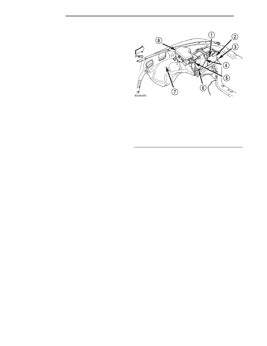
Fig. 18 Power Distribution Center

1 - CLIP
2 - BATTERY
3 - TRAY
4 - NEGATIVE CABLE
5 - POSITIVE CABLE
6 - CLIP
7 - FENDER INNER SHIELD
8 - POWER DISTRIBUTION CENTER

8Fa - 22

STARTING

R1

STARTER MOTOR RELAY (Continued)

HEATED SYSTEMS

TABLE OF CONTENTS

page

page

HEATED GLASS . . . . . . . . . . . . . . . . . . . . . . . . . . . 1

HEATED MIRRORS . . . . . . . . . . . . . . . . . . . . . . . . . 5

HEATED GLASS

TABLE OF CONTENTS

page

page

HEATED GLASS

DESCRIPTION . . . . . . . . . . . . . . . . . . . . . . . . . . . . 1
OPERATION . . . . . . . . . . . . . . . . . . . . . . . . . . . . . 1
DIAGNOSIS AND TESTING . . . . . . . . . . . . . . . . . . 1

REAR WINDOW DEFOGGER SYSTEM . . . . . . . 1

REAR WINDOW DEFOGGER GRID

DESCRIPTION . . . . . . . . . . . . . . . . . . . . . . . . . . . . 2
OPERATION . . . . . . . . . . . . . . . . . . . . . . . . . . . . . 2

DIAGNOSIS AND TESTING . . . . . . . . . . . . . . . . . . 3

REAR WINDOW DEFOGGER GRID . . . . . . . . . . 3

STANDARD PROCEDURE . . . . . . . . . . . . . . . . . . . 3

REAR WINDOW DEFOGGER GRID REPAIR . . . 3

REAR WINDOW DEFOGGER SWITCH

DESCRIPTION . . . . . . . . . . . . . . . . . . . . . . . . . . . . 4
OPERATION . . . . . . . . . . . . . . . . . . . . . . . . . . . . . 4

HEATED GLASS

DESCRIPTION - REAR WINDOW DEFOGGER

The system consists of a rear glass with two verti-

cal bus bars and a series of electrically connected
grid lines fired on the inside surface. A control switch
and a timing circuit are combined into the HVAC
control assembly. A push button on the HVAC control
assembly turns the defroster ON or OFF. Circuit pro-
tection is provided by a cartridge fuse located in the
Power Distribution Center (PDC) for the heated grid
circuit, and a fuse in the fuse block for the control
circuit.

OPERATION - REAR WINDOW DEFOGGER

The defogger system is controlled by a momentary

switch in the HVAC Control assembly, which also
includes the switch for the rear wiper and washer
system. An amber indicator lamp in the HVAC Con-
trol assembly will light to indicate when the defogger
system is turned on. The rear window switch also
contains the defogger system control circuitry includ-
ing the timer logic and the defogger relay.

The defogger system will be automatically turned

off after a programmed time interval of about ten

minutes. After the initial time interval has expired, if
the defogger switch is turned on again during the
same ignition cycle, the defogger system will auto-
matically turn off after about five minutes.

The defogger system will automatically shut off if

the ignition switch is turned to the Off position, or it
can be turned off manually by depressing the defog-
ger switch a second time. Refer to the owner’s man-
ual in the vehicle glove box for more information on
the features, use and operation of the defogger sys-
tem.

DIAGNOSIS AND TESTING - REAR WINDOW
DEFOGGER SYSTEM

For circuit descriptions and diagrams, refer to Rear

Window Defogger in Wiring Diagrams. The operation
of the electrically heated rear window defogger sys-
tem can be confirmed in one of the following man-
ners:

• Turn the ignition switch to the On position.

While monitoring the instrument panel voltmeter, set
the defogger switch in the On position. When the
defogger switch is turned On, a distinct voltmeter
needle deflection should be noted.

AN

HEATED SYSTEMS

8G - 1

• Turn the ignition switch to the On position. Set

the defogger switch in the On position. The rear win-
dow defogger operation can be checked by feeling the
rear window or outside rear view mirror glass. A dis-
tinct difference in temperature between the grid lines
and the adjacent clear glass or the mirror glass can
be detected within three to four minutes of operation.

• Using a 12-volt DC voltmeter, contact the rear

glass heating grid terminal A (right side) with the
negative lead, and terminal B (left side) with the pos-
itive lead (Fig. 1). The voltmeter should read battery
voltage.

The above checks will confirm system operation.

Illumination of the defogger switch indicator lamp
means that there is electrical current available at the
output of the rear window defogger logic and timer
circuitry, but does not confirm that the electrical cur-
rent is reaching the rear glass heating grid lines.

If the defogger system does not operate, the prob-

lem should be isolated in the following manner:

(1) Confirm that the ignition switch is in the On

position.

(2) Ensure that the rear glass heating grid feed

and ground wires are connected to the glass. Confirm
that the ground wire has continuity to ground.

(3) Check the fuses in the Power Distribution Cen-

ter (PDC) and in the junction block. The fuses must
be tight in their receptacles and all electrical connec-
tions must be secure.

When the above steps have been completed and the

rear glass heating grid is still inoperative, one or
more of the following is faulty:

• Rear window switch (HVAC Control Assembly).

• Rear window grid lines (all grid lines would

have to be broken or one of the feed wires discon-
nected for the entire system to be inoperative).

If setting the defogger switch to the On position

produces a severe voltmeter deflection, check for a
short circuit between the rear window switch defog-
ger relay output and the rear glass heating grid.

REAR WINDOW DEFOGGER
GRID

DESCRIPTION - REAR GLASS HEATING GRID

The heated rear window glass has two electrically

conductive vertical bus bars and a series of horizon-
tal grid lines made of a silver-ceramic material,
which is baked on and bonded to the inside surface of
the glass. The grid lines and bus bars comprise a
parallel electrical circuit. A control switch and a tim-
ing circuit are combined into the heating-A/C control
assembly.

A push-button on the heater-A/C control assembly

turns the defroster ON and OFF.

Circuit protection is provided by a cartridge fuse

located in the Power Distribution Center (PDC) for
the heated grid circuit.

OPERATION - REAR GLASS HEATING GRID

When the rear window defogger switch is placed in

the On position, electrical current is directed to the
rear window grid lines through the bus bars. The
grid lines heat the rear window to clear the surface
of fog or snow. Protection for the heating grid circuit
is provided by a fuse in the Power Distribution Cen-
ter (PDC).

The grid lines and bus bars are highly resistant to

abrasion. However, it is possible for an open circuit
to occur in an individual grid line, resulting in no
current flow through the line.

The grid lines can be damaged or scraped off with

sharp instruments. Care should be taken when clean-
ing the glass or removing foreign materials, decals,
or stickers from the glass. Normal glass cleaning sol-
vents or hot water used with rags or toweling is rec-
ommended.

A repair kit is available to repair the grid lines and

bus bars, or to reinstall the heated glass terminals.

Fig. 1 Grid Line Test

1 - VIEW FROM INSIDE VEHICLE
2 - REAR WINDOW DEFOGGER
3 - BUS BARS
4 - VOLTAGE FEED (A)
5 - VOLTMETER
6 - MID-POINT (C)
7 - PICK-UP LEADS
8 - GROUND (B)

8G - 2

HEATED GLASS

AN

HEATED GLASS (Continued)

DIAGNOSIS AND TESTING - REAR WINDOW
DEFOGGER GRID

For circuit descriptions and diagrams, refer to Rear

Window Defogger in Wiring Diagrams. To detect
breaks in the grid lines, the following procedure is
required:

(1) Turn the ignition switch to the On position. Set

the defogger switch in the On position. The indicator
lamp should light. If OK, go to Step 2. If not OK,
(Refer to 8 - ELECTRICAL/HEATED GLASS/REAR
WINDOW DEFOGGER SWITCH - DIAGNOSIS AND
TESTING).

(2) Using a 12-volt DC voltmeter, contact the ver-

tical bus bar on the right side of the vehicle with the
negative lead. With the positive lead, contact the ver-
tical bus bar on the left side of the vehicle. The volt-
meter should read battery voltage. If OK, go to Step
3. If not OK, repair the open circuit to the defogger
relay as required.

(3) With the negative lead of the voltmeter, contact

a good body ground point. The voltage reading should
not change. If OK, go to Step 4. If not OK, repair the
circuit to ground as required.

(4) Connect the negative lead of the voltmeter to

the right side bus bar and touch each grid line at
midpoint C with the positive lead. A reading of
approximately six volts indicates a line is good. A
reading of zero volts indicates a break in the grid
line between midpoint C and the left side bus bar. A
reading of ten to fourteen volts indicates a break
between midpoint C and the right side bus bar. Move
the positive lead on the grid line towards the break
and the voltage reading will change as soon as the
break is crossed.

STANDARD PROCEDURE - REAR WINDOW
DEFOGGER GRID REPAIR

Repair of the rear glass heating grid lines, bus

bars, terminals or pigtail wires can be accomplished
using a Mopar Rear Window Defogger Repair Kit
(Part Number 4267922) or equivalent.

WARNING: MATERIALS CONTAINED IN THE REPAIR
KIT MAY CAUSE SKIN OR EYE IRRITATION. THE
KIT CONTAINS EPOXY RESIN AND AMINE TYPE
HARDENER,

WHICH ARE

HARMFUL

IF

SWAL-

LOWED. AVOID CONTACT WITH THE SKIN AND
EYES. FOR SKIN CONTACT, WASH THE AFFECTED
AREAS WITH SOAP AND WATER. FOR CONTACT
WITH THE EYES, FLUSH WITH PLENTY OF WATER.
DO NOT TAKE INTERNALLY. IF TAKEN INTER-
NALLY, INDUCE VOMITING AND CALL A PHYSICIAN
IMMEDIATELY. USE WITH ADEQUATE VENTILA-
TION. DO NOT USE NEAR FIRE OR FLAME. CON-
TAINS FLAMMABLE SOLVENTS. KEEP OUT OF THE
REACH OF CHILDREN.

(1) Follow the instructions in the repair kit for

preparing the damaged area.

(2) Remove the package separator clamp and mix

the two conductive epoxy components thoroughly
within the packaging. Fold the package in half and
cut the center corner to dispense the epoxy.

(3) For grid line repairs, mask the area to be

repaired with masking tape or a template (Fig. 2).

(4) Apply the epoxy through the slit in the mask-

ing tape or template. Overlap both ends of the break
by at least 19 millimeters (0.75 inch).

(5) For a terminal or pigtail wire replacement,

mask the adjacent areas so the epoxy can be
extended onto the adjacent grid line as well as the
bus bar. Apply a thin layer of epoxy to the area
where the terminal or pigtail wire was fastened and
onto the adjacent grid line.

(6) Apply a thin layer of conductive epoxy to the

terminal or bare wire end of the pigtail and place it
in the proper location on the bus bar. To prevent the
terminal or pigtail wire from moving while the epoxy
is curing, it must be wedged or clamped.

(7) Carefully remove the masking tape or tem-

plate.

CAUTION: Do not allow the glass surface to exceed
204° C (400° F) or the glass may fracture.

(8) Allow the epoxy to cure 24 hours at room tem-

perature, or use a heat gun with a 260° to 371° C
(500° to 700° F) range for fifteen minutes. Hold the
heat gun approximately 25.4 centimeters (10 inches)
from the repair.

(9) After the conductive epoxy is properly cured,

remove the wedge or clamp from the terminal or pig-
tail wire. Do not attach the wire harness connectors
until the curing process is complete.

Fig. 2 Grid Line Repair - Typical

1 - BREAK
2 - GRID LINE
3 - MASKING TAPE

AN

HEATED GLASS

8G - 3

REAR WINDOW DEFOGGER GRID (Continued)


Content   ..  308  309  310  311   ..