Dodge Dakota (R1). Manual - part 302
operating unless the automatic transmission gear
selector is in the Neutral or Park positions.
When the starter relay coil is energized, the nor-
mally open relay contacts close. The relay contacts
connect the relay common feed terminal to the relay
normally open terminal. The closed relay contacts
energize the starter solenoid coil windings.
The energized solenoid pull-in coil pulls in the sole-
noid plunger. The solenoid plunger pulls the shift
lever in the starter motor. This engages the starter
overrunning clutch and pinion gear with the starter
ring gear on the manual transmission flywheel or on
the
automatic
transmission
torque
converter
or
torque converter drive plate.
As the solenoid plunger reaches the end of its
travel, the solenoid contact disc completes the high-
amperage starter feed circuit and energizes the sole-
noid plunger hold-in coil. Current now flows between
the solenoid battery terminal and the starter motor,
energizing the starter.
Once the engine starts, the overrunning clutch pro-
tects the starter motor from damage by allowing the
starter pinion gear to spin faster than the pinion
shaft. When the driver releases the ignition switch to
the On position, the starter relay coil is de-energized.
This causes the relay contacts to open. When the
relay contacts open, the starter solenoid plunger
hold-in coil is de-energized.
When the solenoid plunger hold-in coil is de-ener-
gized, the solenoid plunger return spring returns the
plunger to its relaxed position. This causes the con-
tact disc to open the starter feed circuit, and the shift
lever to disengage the overrunning clutch and pinion
gear from the starter ring gear.
DIAGNOSIS AND TESTING - STARTING
SYSTEM
The battery, starting, and charging systems oper-
ate in conjunction with one another, and must be
tested as a complete system. For correct starting/
charging system operation, all of the components
involved in these 3 systems must perform within
specifications.
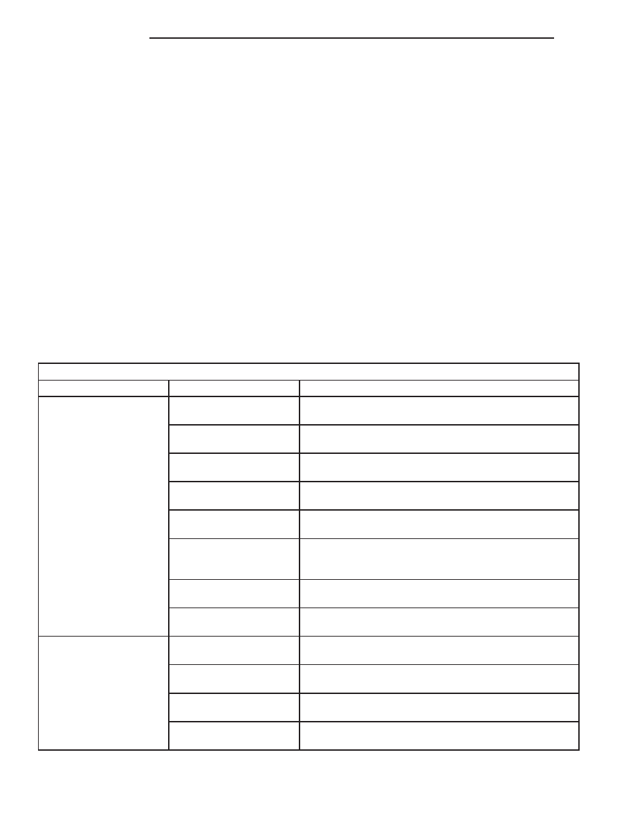
Starting System Diagnosis
CONDITION
POSSIBLE CAUSE
CORRECTION
STARTER FAILS TO
OPERATE.
1. Battery discharged or
faulty.
1. Refer to Battery. Charge or replace battery, if required.
2. Starting circuit wiring
faulty.
2. Refer to 8, Wiring Diagrams. Test and repair starter
feed and/or control circuits, if required.
3. Starter relay faulty.
3. Refer to Starter Relay in the Diagnosis and Testing
section of this group. Replace starter relay, if required.
4. Ignition switch faulty.
4. Refer to Ignition Switch and Key Lock Cylinder.
Replace ignition switch, if required.
5. Clutch pedal position
switch faulty.
5. Refer to Clutch Pedal Position Switch.
6. Park/Neutral position
switch faulty or
misadjusted.
6. Refer to Park/Neutral Position Switch. Replace
park/neutral position switch, if required.
7. Starter solenoid faulty.
7. Refer to Starter Motor. Replace starter motor assembly,
if required.
8. Starter motor faulty.
8. If all other starting system components and circuits test
OK, replace starter motor.
STARTER ENGAGES,
FAILS TO TURN
ENGINE.
1. Battery discharged or
faulty.
1. Refer to Battery. Charge or replace battery, if required.
2. Starting circuit wiring
faulty.
2. Refer to 8, Wiring Diagrams. Test and repair starter
feed and/or control circuits, if required.
3. Starter motor faulty.
3. If all other starting system components and circuits test
OK, replace starter motor assembly.
4. Engine seized.
4. Refer to Engine Diagnosis in the Diagnosis and Testing
section of 9, Engine.
8F - 30
STARTING
AN
STARTING (Continued)