Dodge Dakota (R1). Manual - part 290


  Index      Dodge     Dodge Dakota (R1) - service repair manual 2000 year


Search            


Content   ..  288  289  290  291   ..


Dodge Dakota (R1). Manual - part 290


INSTALLATION

NOTE: If the CAB needs to be replaced, the rear
axle type and tire revolutions per mile must be pro-
gramed into the new CAB. For axle type refer to
Group 3 Differential and Driveline. For tire revolu-
tions per mile refer to Group 22 Tire and Wheels. To
program the CAB refer to the Chassis Diagnostic
Manual.

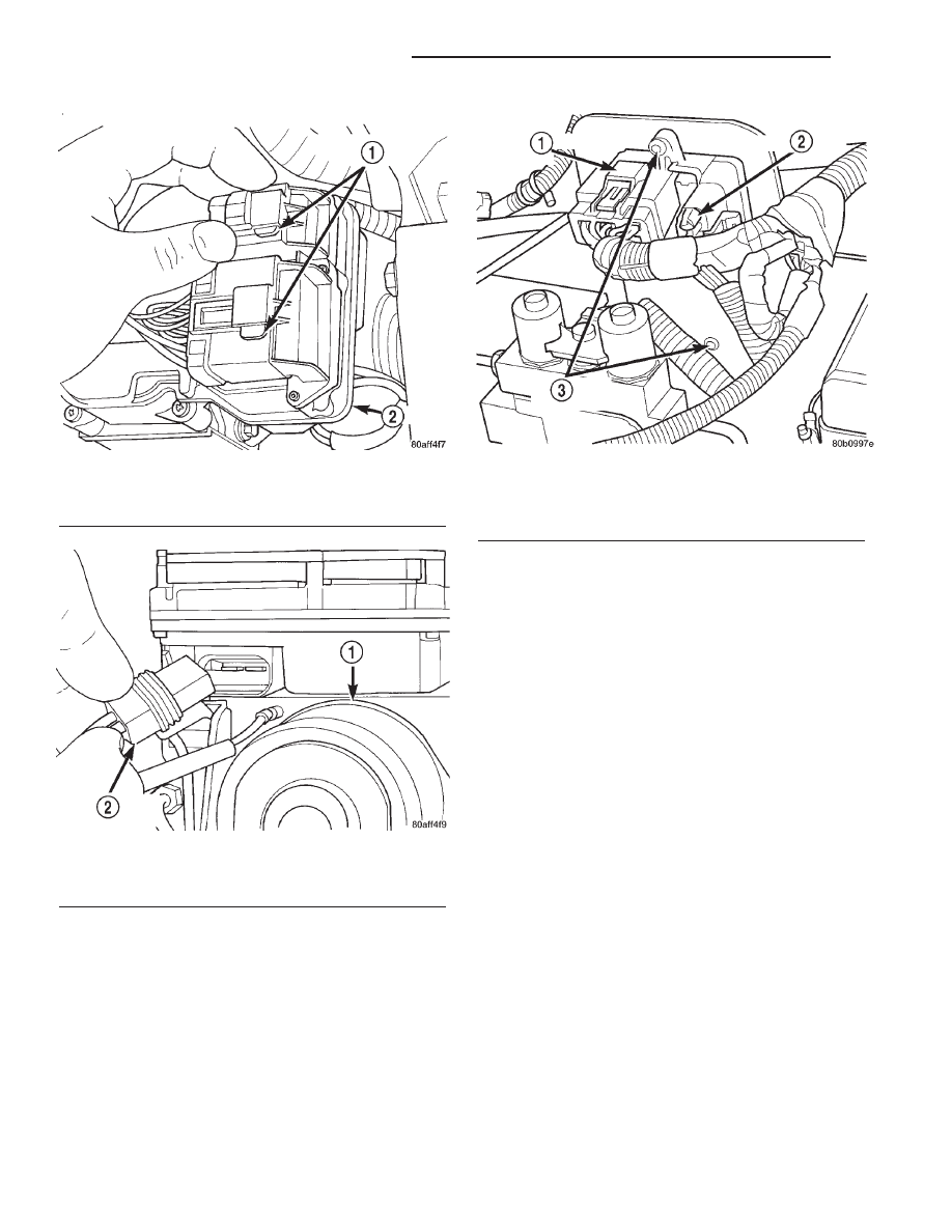
(1) Position the controller on the bracket.

(2) Install the mounting screws and tighten to 6

N·m (53 in. lbs).

(3) Install the RWAL valve harness connector into

the controller.

(4) Install the CAB harness connector into the con-

troller and push down on the connector lock.

DATA LINK CONNECTOR

DESCRIPTION

The data link connector is located at the lower

edge of the instrument panel near the steering col-
umn.

OPERATION

The 16–way data link connector (diagnostic scan

tool connector) links the Diagnostic Readout Box
(DRB) scan tool or the Mopar Diagnostic System
(MDS) with the Powertrain Control Module (PCM).

Fig. 5 Harness Connector Locks

1 - CONNECTOR LOCK
2 - CAB

Fig. 6 Pump Motor Connector

1 - PUMP MOTOR
2 - PUMP CONNECTOR

Fig. 7 RWAL Controller

1 - CAB CONNECTOR LOCK
2 - RWAL CONNECTOR
3 - MOUNTING SCREWS

8E - 10

ELECTRONIC CONTROL MODULES

AN

CONTROLLER ANTILOCK BRAKE (Continued)

POWERTRAIN CONTROL
MODULE

DESCRIPTION

The Powertrain Control Module (PCM) is located

in the engine compartment (Fig. 8). The PCM is
referred to as JTEC.

DESCRIPTION - MODES OF OPERATION

As input signals to the Powertrain Control Module

(PCM) change, the PCM adjusts its response to the
output devices. For example, the PCM must calculate
different injector pulse width and ignition timing for
idle than it does for wide open throttle (WOT).

The PCM will operate in two different modes:

Open Loop and Closed Loop.

During Open Loop modes, the PCM receives input

signals and responds only according to preset PCM
programming. Input from the oxygen (O2S) sensors
is not monitored during Open Loop modes.

During Closed Loop modes, the PCM will monitor

the oxygen (O2S) sensors input. This input indicates
to the PCM whether or not the calculated injector
pulse width results in the ideal air-fuel ratio. This
ratio is 14.7 parts air-to-1 part fuel. By monitoring
the exhaust oxygen content through the O2S sensor,
the PCM can fine tune the injector pulse width. This
is done to achieve optimum fuel economy combined
with low emission engine performance.

The fuel injection system has the following modes

of operation:

• Ignition switch ON

• Engine start-up (crank)

• Engine warm-up

• Idle

• Cruise

• Acceleration

• Deceleration

• Wide open throttle (WOT)

• Ignition switch OFF
The ignition switch On, engine start-up (crank),

engine warm-up, acceleration, deceleration and wide
open throttle modes are Open Loop modes. The idle
and cruise modes, (with the engine at operating tem-
perature) are Closed Loop modes.

IGNITION SWITCH (KEY-ON) MODE

This is an Open Loop mode. When the fuel system

is activated by the ignition switch, the following
actions occur:

• The PCM pre-positions the idle air control (IAC)

motor.

• The PCM determines atmospheric air pressure

from the MAP sensor input to determine basic fuel
strategy.

• The PCM monitors the engine coolant tempera-

ture sensor input. The PCM modifies fuel strategy
based on this input.

• Intake manifold air temperature sensor input is

monitored.

• Throttle position sensor (TPS) is monitored.

• The auto shutdown (ASD) relay is energized by

the PCM for approximately three seconds.

• The fuel pump is energized through the fuel

pump relay by the PCM. The fuel pump will operate
for approximately three seconds unless the engine is
operating or the starter motor is engaged.

• The O2S sensor heater element is energized via

the ASD relay. The O2S sensor input is not used by
the PCM to calibrate air-fuel ratio during this mode
of operation.

ENGINE START-UP MODE

This is an Open Loop mode. The following actions

occur when the starter motor is engaged.

The PCM receives inputs from:
• Battery voltage

• Engine coolant temperature sensor

• Crankshaft position sensor

• Intake manifold air temperature sensor

• Manifold absolute pressure (MAP) sensor

• Throttle position sensor (TPS)

• Starter motor relay

• Camshaft position sensor signal

Fig. 8 PCM Location

1 - RIGHT FRONT FENDER
2 - PCM MOUNTING BOLTS (3)
3 - 32–WAY CONNECTORS (3)
4 - COVER
5 - POWERTRAIN CONTROL MODULE (PCM)

AN

ELECTRONIC CONTROL MODULES

8E - 11

The PCM monitors the crankshaft position sensor.

If the PCM does not receive a crankshaft position
sensor signal within 3 seconds of cranking the
engine, it will shut down the fuel injection system.

The fuel pump is activated by the PCM through

the fuel pump relay.

Voltage is applied to the fuel injectors with the

ASD relay via the PCM. The PCM will then control
the injection sequence and injector pulse width by
turning the ground circuit to each individual injector
on and off.

The PCM determines the proper ignition timing

according to input received from the crankshaft posi-
tion sensor.

ENGINE WARM-UP MODE

This is an Open Loop mode. During engine warm-

up, the PCM receives inputs from:

• Battery voltage

• Crankshaft position sensor

• Engine coolant temperature sensor

• Intake manifold air temperature sensor

• Manifold absolute pressure (MAP) sensor

• Throttle position sensor (TPS)

• Camshaft position sensor signal (in the distribu-

tor)

• Park/neutral switch (gear indicator signal—auto.

trans. only)

• Air conditioning select signal (if equipped)

• Air conditioning request signal (if equipped)
Based on these inputs the following occurs:
• Voltage is applied to the fuel injectors with the

ASD relay via the PCM. The PCM will then control
the injection sequence and injector pulse width by
turning the ground circuit to each individual injector
on and off.

• The PCM adjusts engine idle speed through the

idle air control (IAC) motor and adjusts ignition tim-
ing.

• The PCM operates the A/C compressor clutch

through the clutch relay. This is done if A/C has been
selected by the vehicle operator and requested by the
A/C thermostat.

• When engine has reached operating tempera-

ture, the PCM will begin monitoring O2S sensor
input. The system will then leave the warm-up mode
and go into closed loop operation.

IDLE MODE

When the engine is at operating temperature, this

is a Closed Loop mode. At idle speed, the PCM
receives inputs from:

• Air conditioning select signal (if equipped)

• Air conditioning request signal (if equipped)

• Battery voltage

• Crankshaft position sensor

• Engine coolant temperature sensor

• Intake manifold air temperature sensor

• Manifold absolute pressure (MAP) sensor

• Throttle position sensor (TPS)

• Camshaft position sensor signal (in the distribu-

tor)

• Battery voltage

• Park/neutral switch (gear indicator signal—auto.

trans. only)

• Oxygen sensors
Based on these inputs, the following occurs:
• Voltage is applied to the fuel injectors with the

ASD relay via the PCM. The PCM will then control
injection sequence and injector pulse width by turn-
ing the ground circuit to each individual injector on
and off.

• The PCM monitors the O2S sensor input and

adjusts air-fuel ratio by varying injector pulse width.
It also adjusts engine idle speed through the idle air
control (IAC) motor.

• The PCM adjusts ignition timing by increasing

and decreasing spark advance.

• The PCM operates the A/C compressor clutch

through the clutch relay. This happens if A/C has
been selected by the vehicle operator and requested
by the A/C thermostat.

CRUISE MODE

When the engine is at operating temperature, this

is a Closed Loop mode. At cruising speed, the PCM
receives inputs from:

• Air conditioning select signal (if equipped)

• Air conditioning request signal (if equipped)

• Battery voltage

• Engine coolant temperature sensor

• Crankshaft position sensor

• Intake manifold air temperature sensor

• Manifold absolute pressure (MAP) sensor

• Throttle position sensor (TPS)

• Camshaft position sensor signal (in the distribu-

tor)

• Park/neutral switch (gear indicator signal—auto.

trans. only)

• Oxygen (O2S) sensors
Based on these inputs, the following occurs:
• Voltage is applied to the fuel injectors with the

ASD relay via the PCM. The PCM will then adjust
the injector pulse width by turning the ground circuit
to each individual injector on and off.

• The PCM monitors the O2S sensor input and

adjusts air-fuel ratio. It also adjusts engine idle
speed through the idle air control (IAC) motor.

• The PCM adjusts ignition timing by turning the

ground path to the coil on and off.

• The PCM operates the A/C compressor clutch

through the clutch relay. This happens if A/C has

8E - 12

ELECTRONIC CONTROL MODULES

AN

POWERTRAIN CONTROL MODULE (Continued)

been selected by the vehicle operator and requested
by the A/C thermostat.

ACCELERATION MODE

This is an Open Loop mode. The PCM recognizes

an abrupt increase in throttle position or MAP pres-
sure as a demand for increased engine output and
vehicle acceleration. The PCM increases injector
pulse width in response to increased throttle opening.

DECELERATION MODE

When the engine is at operating temperature, this

is an Open Loop mode. During hard deceleration, the
PCM receives the following inputs.

• Air conditioning select signal (if equipped)

• Air conditioning request signal (if equipped)

• Battery voltage

• Engine coolant temperature sensor

• Crankshaft position sensor

• Intake manifold air temperature sensor

• Manifold absolute pressure (MAP) sensor

• Throttle position sensor (TPS)

• Camshaft position sensor signal (in the distribu-

tor)

• Park/neutral switch (gear indicator signal—auto.

trans. only)

• Vehicle speed sensor
If the vehicle is under hard deceleration with the

proper rpm and closed throttle conditions, the PCM
will ignore the oxygen sensor input signal. The PCM
will enter a fuel cut-off strategy in which it will not
supply a ground to the injectors. If a hard decelera-
tion does not exist, the PCM will determine the
proper injector pulse width and continue injection.

Based on the above inputs, the PCM will adjust

engine idle speed through the idle air control (IAC)
motor.

The PCM adjusts ignition timing by turning the

ground path to the coil on and off.

WIDE OPEN THROTTLE MODE

This is an Open Loop mode. During wide open

throttle operation, the PCM receives the following
inputs.

• Battery voltage

• Crankshaft position sensor

• Engine coolant temperature sensor

• Intake manifold air temperature sensor

• Manifold absolute pressure (MAP) sensor

• Throttle position sensor (TPS)

• Camshaft position sensor signal (in the distribu-

tor)

During wide open throttle conditions, the following

occurs:

• Voltage is applied to the fuel injectors with the

ASD relay via the PCM. The PCM will then control
the injection sequence and injector pulse width by

turning the ground circuit to each individual injector
on and off. The PCM ignores the oxygen sensor input
signal and provides a predetermined amount of addi-
tional fuel. This is done by adjusting injector pulse
width.

• The PCM adjusts ignition timing by turning the

ground path to the coil on and off.

IGNITION SWITCH OFF MODE

When ignition switch is turned to OFF position,

the PCM stops operating the injectors, ignition coil,
ASD relay and fuel pump relay.

DESCRIPTION - 5 VOLT SUPPLIES

Two different Powertrain Control Module (PCM)

five volt supply circuits are used; primary and sec-
ondary.

DESCRIPTION - IGNITION CIRCUIT SENSE

This circuit ties the ignition switch to the Power-

train Control Module (PCM).

DESCRIPTION - POWER GROUNDS

The Powertrain Control Module (PCM) has 2 main

grounds. Both of these grounds are referred to as
power grounds. All of the high-current, noisy, electri-
cal devices are connected to these grounds as well as
all of the sensor returns. The sensor return comes
into the sensor return circuit, passes through noise
suppression, and is then connected to the power
ground.

The power ground is used to control ground cir-

cuits for the following PCM loads:

• Generator field winding

• Fuel injectors

• Ignition coil(s)

• Certain relays/solenoids

• Certain sensors

DESCRIPTION - SENSOR RETURN

The Sensor Return circuits are internal to the Pow-

ertrain Control Module (PCM).

Sensor Return provides a low–noise ground refer-

ence for all engine control system sensors. Refer to
Power Grounds for more information.

DESCRIPTION - SIGNAL GROUND

Signal ground provides a low noise ground to the

data link connector.

OPERATION

The PCM operates the fuel system. The PCM is a

pre-programmed, triple microprocessor digital com-
puter. It regulates ignition timing, air-fuel ratio,
emission control devices, charging system, certain
transmission features, speed control, air conditioning

AN

ELECTRONIC CONTROL MODULES

8E - 13

POWERTRAIN CONTROL MODULE (Continued)


Content   ..  288  289  290  291   ..