Dodge Dakota (R1). Manual - part 276


  Index      Dodge     Dodge Dakota (R1) - service repair manual 2000 year


Search            


Content   ..  274  275  276  277   ..


Dodge Dakota (R1). Manual - part 276


CAUTION: Radiator pressure testing tools are very
sensitive to small air leaks, which will not cause
cooling system problems. A pressure cap that does
not have a history of coolant loss should not be
replaced just because it leaks slowly when tested
with this tool. Add water to tool. Turn tool upside
down and recheck pressure cap to confirm that cap
needs replacement.

CLEANING

Use only a mild soap and water to clean the radi-

ator cap. Using any type solvent may cause damage
to the seal in the radiator cap.

INSPECTION

Hold cap at eye level, right side up. The vent valve

(Fig. 29) at bottom of cap should open. If rubber gas-
ket has swollen and prevents vent valve from open-
ing, replace cap.

Hold cap at eye level, upside down. If any light can

be seen between vent valve and rubber gasket,
replace cap. Do not use a replacement cap that
has a spring to hold vent shut. 
A replacement cap
must be the type designed for a coolant reserve/over-
flow system with a completely sealed diaphragm
spring and a rubber gasket. This gasket is used to
seal to radiator filler neck top surface. Use of proper
cap will allow coolant return to radiator.

RADIATOR COOLANT FLOW
CHECK

DIAGNOSIS AND TESTING - RADIATOR
COOLANT FLOW CHECK

Use the following procedure to determine if coolant

is flowing through cooling system.

(1) Idle

engine

until

operating

temperature

is

reached. If upper radiator hose is warm to the touch,
thermostat is opening and coolant is flowing to radiator.

WARNING: HOT, PRESSURIZED COOLANT CAN
CAUSE INJURY BY SCALDING. USING A RAG TO
COVER RADIATOR PRESSURE CAP, OPEN RADIA-
TOR CAP SLOWLY TO FIRST STOP. ALLOW ANY
BUILT-UP PRESSURE TO VENT TO THE RESERVE/
OVERFLOW TANK. AFTER PRESSURE BUILD-UP
HAS

BEEN

RELEASED,

REMOVE

CAP

FROM

FILLER NECK.

(2) Drain a small amount of coolant from radiator

until ends of radiator tubes are visible through filler
neck. Idle engine at normal operating temperature. If
coolant is flowing past exposed tubes, coolant is cir-
culating.

RADIATOR DRAINCOCK

REMOVAL

WARNING: DO NOT LOOSEN RADIATOR DRAIN-
COCK WITH SYSTEM HOT AND PRESSURIZED.
SERIOUS BURNS FROM COOLANT CAN OCCUR.
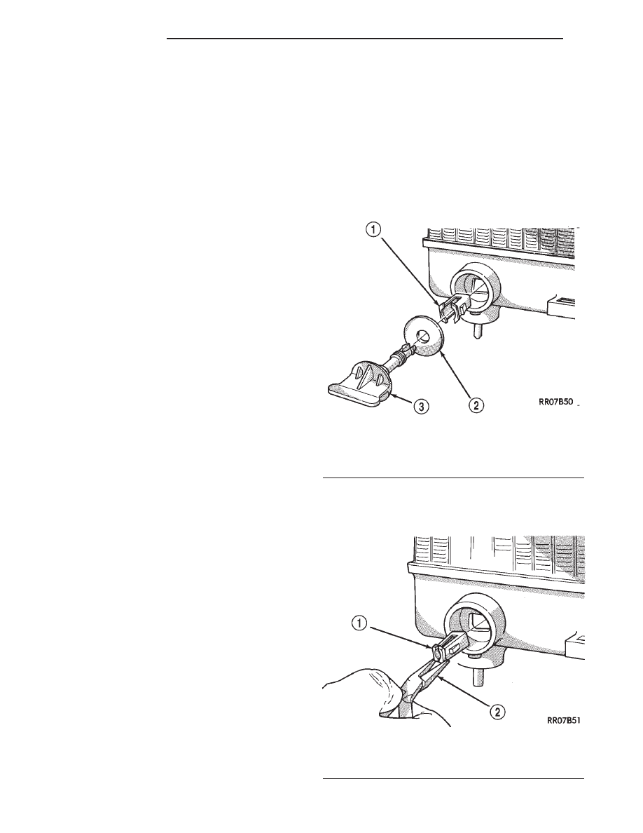
(1) Unscrew

draincock

stem

(counterclockwise

rotation). When stem is completely unscrewed, pull it
from radiator tank and draincock body (Fig. 26).

(2) Using a pair of needle nose pliers, compress

draincock body and pull straight out of radiator (Fig.
27).

Fig. 26 Draincock Assembly

1 - BODY
2 - SEAL
3 - STEM

Fig. 27 Draincock Body Removal

1 - DRAINCOCK BODY
2 - NEEDLE NOSE PLIERS

7a - 50

5.2L ENGINE

R1

RADIATOR CAP (Continued)

INSTALLATION

(1) Install draincock stem loosely into body (Fig.

28). The draincock assembly cannot be installed if
stem is threaded into the body.

(2) Push draincock assembly into opening in radi-

ator tank. It will snap into place when fully seated.

(3) Tighten draincock (clockwise) to 2.0 to 2.7 N·m

(18-25 in. lbs.) torque.

RADIATOR PRESSURE CAP

DESCRIPTION

All radiators are equipped with a pressure cap.

This cap releases pressure at some point within a
range of 124-to-145 kPa (18-to-21 psi). The pressure
relief point (in pounds) is engraved on top of the cap

The cooling system will operate at pressures

slightly above atmospheric pressure. This results in a
higher coolant boiling point allowing increased radi-
ator cooling capacity. The cap contains a spring-
loaded pressure relief valve. This valve opens when
system pressure reaches the release range of 124-to-
145 kPa (18-to-21 psi).

A rubber gasket seals the radiator filler neck. This

is done to maintain vacuum during coolant cool-down
and to prevent leakage when system is under pres-
sure (Fig. 29).

OPERATION

A vent valve in the center of the cap will remain

shut as long as the cooling system is pressurized. As
the coolant cools, it contracts and creates a vacuum
in cooling system. This causes the vacuum valve to
open and coolant in reserve/overflow tank to be
drawn through connecting hose into radiator. If the
vacuum valve is stuck shut, or overflow hose is
kinked, radiator hoses will collapse on cool-down.

VISCOUS FAN DRIVE

DESCRIPTION

CAUTION: Engines equipped with accessory drive
belts have reverse rotating fans and viscous fan
drives. They are marked with the word REVERSE to
designate their usage. Installation of the wrong fan
or viscous fan drive can result in engine overheat-
ing.

The thermal viscous fan drive is a silicone-fluid-

filled coupling used to connect the fan blades to the
water pump shaft. The coupling allows the fan to be
driven in a normal manner. This is done at low
engine speeds while limiting the top speed of the fan
to a predetermined maximum level at higher engine
speeds (Fig. 30).

On all 4.7L an electrical cooling fan located in the

fan shroud aids in low speed cooling, It is designed to
augment the viscous fan, However, it does not
replace the viscous fan.

Fig. 28 Draincock Assembled for Installation

1 - STEM
2 - BODY LOOSE ON STEM

Fig. 29 Radiator Pressure Cap - Typical

1 - FILLER NECK SEAL
2 - VACUUM VENT VALVE
3 - PRESSURE RATING
4 - PRESSURE VALVE

R1

5.2L ENGINE

7a - 51

RADIATOR DRAINCOCK (Continued)

A thermostatic bimetallic spring coil is located on

the front face of the viscous fan drive unit. This
spring coil reacts to the temperature of the radiator
discharge air. It engages the viscous fan drive for
higher fan speed if the air temperature from the
radiator rises above a certain point. Until additional
engine cooling is necessary, the fan will remain at a
reduced rpm regardless of engine speed (Fig. 31).

OPERATION

When sufficient heat is present, the viscous fan

drive will engage. This is when the air flowing
through the radiator core causes a reaction to the

bimetallic coil. It then increases fan speed to provide
the necessary additional engine cooling.

Once the engine has cooled, the radiator discharge

temperature will drop. The bimetallic coil again
reacts and the fan speed is reduced to the previous
disengaged speed.

DIAGNOSIS AND TESTING - VISCOUS FAN
DRIVE

If the fan assembly free-wheels without drag (the

fan blades will revolve more than five turns when
spun by hand), replace the fan drive. This spin test
must be performed when the engine is cool.

For the following test, the cooling system must be

in good condition. It also will ensure against exces-
sively high coolant temperature.

WARNING: BE SURE THAT THERE IS ADEQUATE
FAN BLADE CLEARANCE BEFORE DRILLING.

(1) Drill a 3.18-mm (1/8-in) diameter hole in the

top center of the fan shroud.

(2) Obtain a dial thermometer with an 8 inch stem

(or equivalent). It should have a range of -18° to
105°C (0° to 220° F). Insert thermometer through the
hole in the shroud. Be sure that there is adequate
clearance from the fan blades.

(3) Connect a tachometer and an engine ignition

timing light (timing light is to be used as a strobe
light).

(4) Block the air flow through the radiator. Secure

a sheet of plastic in front of the radiator (or air con-
ditioner condenser). Use tape at the top to secure the
plastic and be sure that the air flow is blocked.

(5) Be sure that the air conditioner (if equipped) is

turned off.

WARNING: USE EXTREME CAUTION WHEN THE
ENGINE IS OPERATING. DO NOT STAND IN A
DIRECT LINE WITH THE FAN. DO NOT PUT YOUR
HANDS NEAR THE PULLEYS, BELTS OR FAN. DO
NOT WEAR LOOSE CLOTHING.

(6) Start the engine and operate at 2400 rpm.

Within ten minutes the air temperature (indicated on
the dial thermometer) should be up to 88° C (190° F).
Fan drive engagement should have started to occur
at between 74° to 82° C (165° to 180° F). Engage-
ment is distinguishable by a definite increase in fan
flow noise (roaring). The timing light also will indi-
cate an increase in the speed of the fan.

(7) When the air temperature reaches 88° C (190°

F), remove the plastic sheet. Fan drive disengage-
ment 
should have started to occur at between 57° to
79° C (135° to 175° F). A definite decrease of fan
flow noise (roaring) should be noticed. If not, replace
the defective viscous fan drive unit.

Fig. 30 Fan Blade/Viscous Fan Drive - 4.7L/5.2L/5.9L

Engines

1 - VISCOUS FAN DRIVE
2 - FAN BLADE
3 - SCREW AND WASHER

Fig. 31 Viscous Fan Drive - 4.7L/5.2L/5.9L Engines -

Typical

1 - VISCOUS FAN DRIVE
2 - THERMOSTATIC SPRING
3 - MOUNTING NUT TO WATER PUMP HUB

7a - 52

5.2L ENGINE

R1

VISCOUS FAN DRIVE (Continued)

REMOVAL

(1) Disconnect battery negative cable.
(2) The thermal viscous fan drive/fan blade assem-

bly is attached (threaded) to water pump hub shaft
(Fig. 33). Remove fan blade/viscous fan drive assem-
bly from water pump by turning mounting nut coun-
terclockwise as viewed from front. Threads on
viscous fan drive are RIGHT HAND. A Snap-On 36
MM Fan Wrench (number SP346 from Snap-On
Cummins Diesel Tool Set number 2017DSP) and Spe-
cial Tool 6958 Spanner Wrench with Adapter Pins
8346 can be used to hold the pulley still. (Fig. 32) to
prevent pulley from rotating.

(3) Do not attempt to remove fan/viscous fan drive

assembly from vehicle at this time.

(4) Do not unbolt fan blade assembly (Fig. 34)

from viscous fan drive at this time.

(5) Remove upper fan shroud attaching hardware

(Fig. 35).

(6) Remove upper fan shroud and fan blade/viscous

fan drive from vehicle.

(7) After removing fan blade/viscous fan drive

assembly, do not place viscous fan drive in horizon-
tal position. If stored horizontally, silicone fluid in
the viscous fan drive could drain into its bearing
assembly and contaminate lubricant.

(8) Remove four bolts securing fan blade assembly

to viscous fan drive (Fig. 34).

Fig. 32 Fan Blade and Viscous Fan Drive Removal

1 - SPECIAL TOOL 6958 SPANNER WRENCH WITH ADAPTER
PINS 8346
2 - FAN

Fig. 33 Fan Blade/Viscous Fan Drive—4.7L/5.2L/5.9L

Engine

1 - FAN AND VISCOUS DRIVE
2 - WATER PUMP THREADED SHAFT

Fig. 34 Viscous Fan Drive and Fan Blade

1 - VISCOUS FAN DRIVE
2 - FAN BLADE
3 - SCREW AND WASHER

R1

5.2L ENGINE

7a - 53

VISCOUS FAN DRIVE (Continued)


Content   ..  274  275  276  277   ..