Dodge Dakota (R1). Manual - part 205


  Index      Dodge     Dodge Dakota (R1) - service repair manual 2000 year


Search            


Content   ..  203  204  205  206   ..


Dodge Dakota (R1). Manual - part 205


AXLE BEARINGS

REMOVAL

(1) Remove the axle shaft.
(2) Remove the axle shaft seal and bearing from

the axle tube with Bearing Removal Tool C-4660-A.

(3) Inspect the axle shaft tube bore for roughness

and burrs. Remove as necessary.

INSTALLATION

(1) Wipe the axle shaft tube bore clean.
(2) Install axle shaft bearing with Installer 5063

and Handle C-4171.

(3) Install a new axle shaft seal with Installer

8402 and Handle C-4171.

(4) Install the axle shaft.

PINION SEAL

REMOVAL

(1) Raise and support the vehicle.
(2) Remove skid plate, if equipped.
(3) Remove both C/V driveshafts.
(4) Mark the propeller shaft and pinion companion

flange for installation reference.

(5) Remove the front propeller shaft.
(6) Rotate the pinion gear three or four times and

verify pinion rotates smoothly.

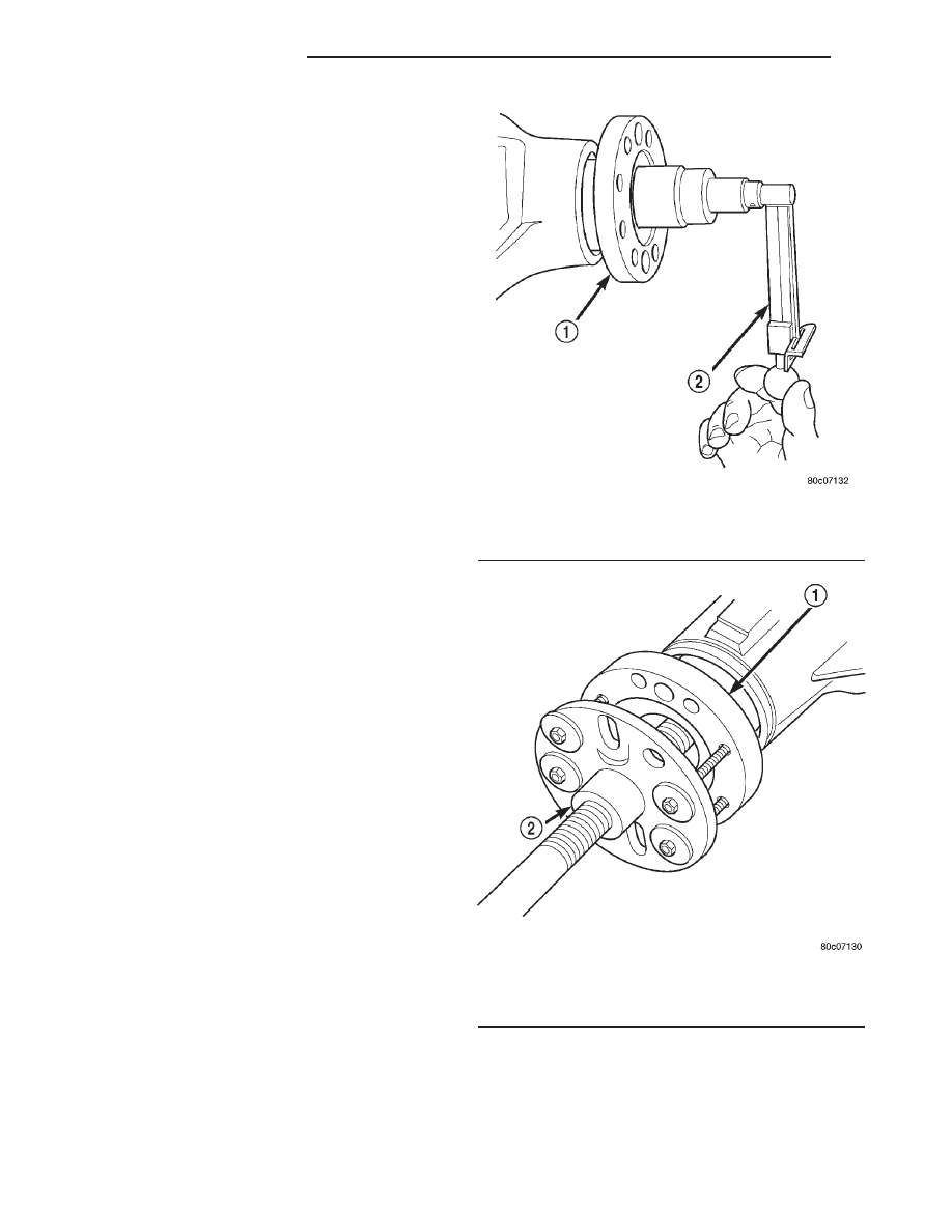
(7) Record rotating torque at the pinion with an

inch pound torque wrench, for installation reference
(Fig. 20).

(8) Remove the companion flange with Remover

C-452 (Fig. 21).

(9) Position Holder 6719 against the companion

flange and install a four bolts and washers into the
threaded holes and tighten the bolts.

(10) Remove the pinion nut.
(11) Remove the companion flange with Remover

C-452 (Fig. 21).

(12) Remove pinion seal with a pry tool or a slide

hammer mounted screw.

INSTALLATION

NOTE: Outer perimeter of pinion seal is pre-coated
with a special sealant.

(1) Apply a light coating of gear lubricant on the

lip of pinion seal.

(2) Install seal with Installer C-3972-A and Handle

C-4171 (Fig. 22).

(3) Install the companion flange onto the pinion

with Installer C-3718 and Holder 6719A.

(4) Position holder against the companion flange

and install four bolts and washers into the threaded

holes. Tighten the bolt and washer so that the holder
is held to the flange.

(5) Install the new pinion nut onto the pinion shaft

and tighten the pinion nut until there is zero bearing
end-play (Fig. 23).

Fig. 20 Pinion Rotating Torque

1 - COMPANION FLANGE
2 - INCH POUND TORQUE WRENCH

Fig. 21 Companion Flange Remover

1 - COMPANION FLANGE
2 - PULLER TOOL

3 - 38

FRONT AXLE - C205F

AN

CAUTION: Do not exceed the minimum tightening
torque when installing the companion flange at this
point. Damage to the collapsible spacer or bearings
may result.

(6) Tighten the nut to 271 N·m (200 ft. lbs.).

CAUTION: Never loosen pinion nut to decrease pin-
ion bearing rotating torque and never exceed spec-
ified preload torque. If preload torque or rotating
torque is exceeded a new collapsible spacer must
be installed.

(7) Rotate and record the axle rotating torque at

the pinion shaft using a torque wrench. The rotating
torque should be equal to the reading recorded dur-
ing removal plus an additional 0.56 N·m (5 in. lbs.)
(Fig. 24).

(8) If the rotating torque is low, tighten the pinion

nut in 6.8 N·m (5 ft. lbs.) increments until the proper
rotating torque is achieved.

CAUTION: If the maximum tightening torque is
reached prior to reaching the required rotating
torque, the collapsible spacer may have been dam-
aged. Replace the collapsible spacer.

(9) Install the propeller shaft with reference marks

aligned.

(10) Add gear lubricant to differential housing if

necessary.

(11) Install C/V driveshafts.
(12) Install skid plate, if equipped.
(13) Lower the vehicle.

DIFFERENTIAL

REMOVAL

(1) Raise and support vehicle.
(2) Remove the differential housing cover and

allow fluid to drain.

(3) Remove the axle shafts.

Fig. 22 Pinion Seal Installer

1 - HANDLE
2 - INSTALLER

Fig. 23 Companion Flange Holder

1 - DIFFERENTIAL HOUSING
2 - COMPANION FLANGE HOLDER
3 - TORQUE WRENCH

Fig. 24 Check Pinion Rotation Torque

1 - COMPANION FLANGE
2 - INCH POUND TORQUE WRENCH

AN

FRONT AXLE - C205F

3 - 39

PINION SEAL (Continued)

(4) Note differential bearing cape reference num-

bers stamped on caps and machined flat on the hous-
ing. If reference numbers cannot be found, make new
marks for later reference.

(5) Loosen the bearing cap bolts.
(6) Install Adapter Plates 8142-A onto the axle

housing.

(7) Position Spreader W-129-B onto the adapter

plates and install the safety holddown clamps.
Tighten the tool turnbuckle finger-tight.

(8) Install a Pilot Stud L-4438 at the left side of

the differential housing. Attach Dial Indicator C-3339
to pilot stud. Load the indicator plunger against the
opposite side of the housing and zero the indicator.

(9) Spread the housing to remove the differential

case from the housing. Measure the distance with the
dial indicator (Fig. 25).

CAUTION: Do not spread over 0.34 mm (0.013 in). If
the housing is over-spread, it could be distorted or
damaged.

(10) Remove the dial indicator.
(11) While holding the differential case in position,

remove bearing cap bolts and caps.

(12) Remove the differential from the housing.

Ensure that the differential bearing cups and shims
remain in position on the differential bearings.

(13) Tag differential bearing cups and shims to

indicate their location.

(14) Remove spreader from housing.

DISASSEMBLY

(1) Remove ring gear.
(2) Remove roll-pin holding mate shaft in housing.
(3) Remove pinion gear mate shaft.
(4) Rotate differential side gears and remove the

pinion mate gears and thrust washers (Fig. 26).

(5) Remove the differential side gears and thrust

washers.

ASSEMBLY

(1) Install the differential side gears and thrust

washers.

(2) Install the pinion mate gears and thrust wash-

ers.

(3) Install the pinion gear mate shaft.
(4) Align the hole in the pinion gear mate shaft

with the hole in the differential case.

(5) Install the roll-pin in the differential case a

punch and hammer (Fig. 27). Peen the edge of the
roll-pin hole in the differential case in two places
180° apart.

(6) Lubricate

all

differential

components

with

hypoid gear lubricant.

(7) Install ring gear.

Fig. 25 Spread Axle Housing-Typical

1 - DIAL INDICATOR
2 - SPREADER

Fig. 26 Pinion Mate Gear

1 - THRUST WASHER
2 - SIDE GEAR
3 - PINION MATE GEAR

3 - 40

FRONT AXLE - C205F

AN

DIFFERENTIAL (Continued)

INSTALLATION

If replacement differential bearings or differential

case are replaced, Refer to adjustments fore Differen-
tial Bearing Preload and Gear Backlash procedures.

(1) Install Spreader W-129-B, with the Adapter

Plates 8142-A, on the axle and install the safety
holddown clamps. Tighten the tool turnbuckle finger–
tight.

(2) Install a Pilot Stud L-4438 at the left side of

the differential housing. Attach Dial Indicator C-3339
to pilot stud. Load the indicator plunger against the
opposite side of the housing and zero the indicator.

(3) Spread the housing to install the differential

case and preload shims in the housing. Measure the
distance with the dial indicator.

CAUTION: Do not spread over 0.34 mm (0.013 in). If
the housing is over-spread, it could be distorted or
damaged.

(4) Remove the dial indicator.
(5) Install differential case in the housing. Ensure

differential bearing cups remain in position on the
bearings and the differential preload shims are
seated in the housing. Tap differential case to ensure
bearings cups are seated in the housing.

(6) Install bearing caps to their original locations

and loosely install cap bolts.

(7) Remove axle housing spreader.

(8) Tighten the bearing cap bolts to 61 N·m (45 ft.

lbs.).

(9) Install the axle shafts.
(10) Install the differential housing cover and fill

with the correct lubricant.

DIFFERENTIAL CASE
BEARINGS

REMOVAL

(1) Remove differential from axle housing.
(2) Remove bearings from the differential case

with Puller/Press C-293-PA , Adapters C-293-48 and
Plug C-293-3 (Fig. 28).

INSTALLATION

(1) Install differential side bearings with Installer

C-3716-A and Handle C-4171 (Fig. 29).

(2) Install differential in axle housing.

Fig. 27 Pinion Mate Shaft Roll-Pin

1 - PUNCH
2 - PINION MATE SHAFT
3 - MATE SHAFT LOCKPIN

Fig. 28 Differential Bearing Puller

1 - PULLER
2 - ADAPTERS
3 - BEARING
4 - DIFFERENTIAL
5 - PLUG

AN

FRONT AXLE - C205F

3 - 41

DIFFERENTIAL (Continued)


Content   ..  203  204  205  206   ..