Dodge Dakota (R1). Manual - part 198
CENTER BEARING ADJUSTMENT
Drive away shudder is a vibration that occurs at
first acceleration from a stop. Shudder vibration usu-
ally peaks at the engines highest torque output.
Shudder is a symptom associated with vehicles using
a two-piece propeller shaft. To decrease shudder,
lower the center bearing in 1/8 inch increments. Use
shim stock or fabricated plates. Plate stock must be
used to maintain compression of the rubber insulator
around the bearing. Do not use washers. Replace the
original bolts with the appropriate increased length
bolts.
SINGLE CARDAN UNIVERSAL
JOINTS
DISASSEMBLY
NOTE: The following procedure is described for a
propeller shaft equipped with only a cardan joint in
the tube yoke. If the propeller shaft is equipped
with a companion yoke, simply repeat the following
steps to remove the cardan joint from the compan-
ion yoke after removing the cardan joint from the
tube yoke.
Individual components of cardan universal joints
are not serviceable. If worn or leaking, they must be
replaced as an assembly.
(1) Remove the propeller shaft.
(2) Using a soft drift, tap the outside of the bear-
ing cap assembly to loosen snap ring.
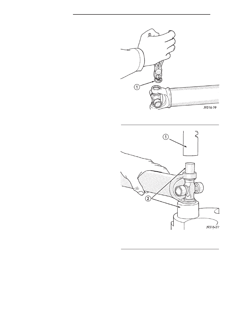
(3) Remove snap rings from both sides of yoke
(Fig. 15).
(4) Set the yoke in an arbor press or vise with a
socket whose inside diameter is large enough to
receive the bearing cap positioned beneath the yoke.
(5) Position the yoke with the grease fitting, if
equipped, pointing up.
(6) Place
a
socket
with
an
outside
diameter
smaller than the upper bearing cap on the upper
bearing cap and press the cap through the yoke to
release the lower bearing cap (Fig. 16).
(7) If the bearing cap will not pull out of the yoke
by hand after pressing, tap the yoke ear near the
bearing cap to dislodge the cap.
(8) To remove the opposite bearing cap, turn the
yoke over and straighten the cross in the open hole.
Then, carefully press the end of the cross until the
remaining bearing cap can be removed (Fig. 17).
CAUTION: If the cross or bearing cap are not
straight during installation, the bearing cap will
score the walls of the yoke bore and damage can
occur.
Fig. 15 Snap Ring
1 - SNAP RING
Fig. 16 Press Out Bearing
1 - PRESS
2 - SOCKET
3 - 10
PROPELLER SHAFT
AN
CENTER BEARING (Continued)