Dodge Dakota (R1). Manual - part 72


  Index      Dodge     Dodge Dakota (R1) - service repair manual 2000 year


Search            


Content   ..  70  71  72  73   ..


Dodge Dakota (R1). Manual - part 72


Symptom:

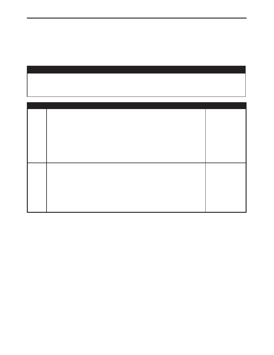
*VTSS INDICATOR INOPERATIVE

POSSIBLE CAUSES

VTSS INDICATOR LAMP OPEN

VTSS INDICATOR DRIVER CIRCUIT OPEN

CENTRAL TIMER MODULE - INTERNAL MALFUNCTION

TEST

ACTION

APPLICABILITY

1

Disconnect the instrument cluster C1 harness connector.
Using a 12-volt test light connected to 12-volts, check the VTSS Indicator Driver
circuit at the instrument cluster connector.
Turn the ignition on.
With the DRBIII

t in Vehicle Theft, actuate the VTSS Indicator.

Does the test light illuminate when the VTSS Indicator is actuated?

All

Yes

Replace the instrument cluster.
Perform VTSS VERIFICATION TEST - 1A.

No

Go To

2

2

Disconnect the Instrument Cluster C1 harness connector.
Disconnect the CTM C1 harness connector.
Measure the resistance of the VTSS Indicator Driver circuit.
Is the resistance below 5.0 ohms?

All

Yes

Replace the Central Timer Module.
Perform VTSS VERIFICATION TEST - 1A.

No

Repair the VTSS Indicator Driver circuit for an open.
Perform VTSS VERIFICATION TEST - 1A.

285

VEHICLE THEFT/SECURITY

Symptom:

*VTSS WILL NOT ARM

POSSIBLE CAUSES

IMPROPER VTSS STATUS

IMPROPER VTSS ARMING INHIBITORS

CENTRAL TIMER MODULE - INTERNAL MALFUNCTION

TEST

ACTION

APPLICABILITY

1

With the DRBIII

t, check that the Theft Alarm is enabled.

Was the Theft Alarm enabled?

All

Yes

Go To

2

No

With the DRBIII

t, enable the Vehicle Theft Security System

(VTSS).
Perform VTSS VERIFICATION TEST - 1A.

2

Make sure all doors are closed.
With the DRBIII

t, read the Door Ajar Switch states.

Do any of the Door Ajar Switch states read CLOSED?

All

Yes

Correct the arming inhibitor or refer to the Symptom List and
diagnose the appropriate symptom.
Perform VTSS VERIFICATION TEST - 1A.

No

Replace the Central Timer Module.
Perform VTSS VERIFICATION TEST - 1A.

286

VEHICLE THEFT/SECURITY

Symptom:

FRONT WIPER MODE SWITCH SENSE CIRCUIT SHORT TO
GROUND

When Monitored and Set Condition:

FRONT WIPER MODE SWITCH SENSE CIRCUIT SHORT TO GROUND

When Monitored:

Ignition On.

Set Condition:

Central Timer Module detects a short to ground on the Front Wiper Mode

Switch sense circuit.

POSSIBLE CAUSES

INTERMITTENT WIRING AND CONNECTORS

FRONT WIPER INTERMITTENT MODE SENSE CIRCUIT SHORT TO GROUND

FUSED IGNITION SWITCH OUTPUT SHORT TO GROUND

JUNCTION BLOCK SHORT TO GROUND

FRONT WIPER SWITCH SHORT TO GROUND

CENTRAL TIMER MODULE

TEST

ACTION

APPLICABILITY

1

Turn the ignition on.
With the DRBIII

t, erase DTCs.

Cycle the ignition off and on, leaving ignition key on for at least 15 seconds.
Operate the Wiper system in all modes.
With the DRBIII

t, read DTCs.

Does the DTC reset?

All

Yes

Go To

2

No

Go To

6

2

Turn the ignition off.
Disconnect the Front Wiper Switch.
Disconnect the Central Timer Module.
Measure the resistance between ground and the Front Wiper Intermittent Mode
Sense circuit
Is the resistance below 5.0 ohms?

All

Yes

Repair the Front Wiper Intermittent Mode Sense Circuit for a
short to Ground.
Perform BODY VERIFICATION TEST - VER 1.

No

Go To

3

287

WINDSHIELD WIPER & WASHER

TEST

ACTION

APPLICABILITY

3

Turn the ignition off.
Disconnect the Front Wiper Switch.
Disconnect the C8 Junction Block harness connector.
Measure the resistance between ground and the Fused Ignition Switch Output
circuit
Is the resistance below 5.0 ohms?

All

Yes

Repair the Fused Ignition Switch Output circuit for a short to
Ground.
Perform BODY VERIFICATION TEST - VER 1.

No

Go To

4

4

Turn the ignition off.
Disconnect the C8 Junction Block harness connector..
Replace the circuit fuse.
Turn the ignition on.
Inspect the circuit fuse for an open.
Is the fuse Open?

All

Yes

Repair the Junction Block or other shared fused circuits for a
short to Ground.
Perform BODY VERIFICATION TEST - VER 1.

No

Go To

5

5

Turn the ignition off.
Disconnect the Central Timer Module harness connector.
Disconnect the C8 Junction Block harness connector.
Turn the Front Wiper Switch to the Intermittent selection.
Measure the resistance between ground and the Front Wiper Intermittent Mode
Sense circuit.
Is the resistance below 5.0 ohms?

All

Yes

Replace the Front Wiper Switch (Multi- Function Switch) in
accordance with the Service Information.
Perform BODY VERIFICATION TEST - VER 1.

No

Replace the Central Timer module in accordance with the Service
Information.
Perform BODY VERIFICATION TEST - VER 1.

6

The conditions necessary to set this DTC are not present at this time.
Using the schematics as a guide, inspect the wiring and connectors specific to this
circuit.
Wiggle the wiring while checking for shorts and open circuits.
Were there any problems found?

All

Yes

Repair as necessary.
Perform BODY VERIFICATION TEST - VER 1.

No

Test Complete.

288

WINDSHIELD WIPER & WASHER

FRONT WIPER MODE SWITCH SENSE CIRCUIT SHORT TO GROUND —

Continued


Content   ..  70  71  72  73   ..