Dodge Dakota (ND). Manual - part 461


  Index      Dodge     Dodge Dakota (ND) 2005 - service repair manual 2005 year


Search            


Content   ..  459  460  461  462   ..


Dodge Dakota (ND). Manual - part 461


The ORC microprocessor continuously monitors all of the side passive restraint system electrical circuits to deter-
mine the system readiness. If the ORC detects a monitored system fault, it sets a Diagnostic Trouble Code (DTC)
and controls the airbag indicator operation accordingly. The impact sensors each receive battery current and ground
through left or right sensor plus and minus circuits from the ORC. The impact sensors and the ORC communicate
by modulating the voltage in the sensor plus circuit.

The hard wired circuits between the side impact sensors and the ORC may be diagnosed and tested using con-
ventional diagnostic tools and procedures. However, conventional diagnostic methods will not prove conclusive in
the diagnosis of the ORC, the impact sensors, or the electronic message inputs to or outputs from the impact sen-
sors. The most reliable, efficient, and accurate means to diagnose the impact sensors, the ORC, and the electronic
message communication between the sensors and the ORC requires the use of a diagnostic scan tool. Refer to the
appropriate diagnostic information.

REMOVAL

FRONT

WARNING: To avoid personal injury or death, on vehicles equipped with airbags, disable the supplemental
restraint system before attempting any steering wheel, steering column, airbag, occupant classification sys-
tem, seat belt tensioner, impact sensor, or instrument panel component diagnosis or service. Disconnect
and isolate the battery negative (ground) cable, then wait two minutes for the system capacitor to discharge
before performing further diagnosis or service. This is the only sure way to disable the supplemental
restraint system. Failure to take the proper precautions could result in accidental airbag deployment.

WARNING: To avoid personal injury or death, never strike or drop the front impact sensor, as it can damage
the impact sensor or affect its calibration. The front impact sensor enables the system to deploy the front
supplemental restraints. If an impact sensor is accidentally dropped during service, the sensor must be
scrapped and replaced with a new unit. Failure to observe this warning could result in accidental, incom-
plete, or improper front supplemental restraint deployment.

1. Disconnect and isolate the battery negative cable.

Wait two minutes for the system capacitor to dis-
charge before further service.

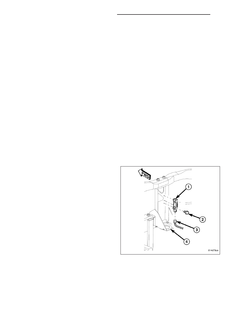
2. Remove the two screws (2) that secure the right or

left front impact sensor (1) to the back of the right
or left radiator support vertical member (4).

3. Disconnect the headlamp and dash wire harness

connector (3) from the sensor connector recepta-
cle.

4. Remove the right or left front impact sensor from

the engine compartment.

8O - 440

RESTRAINTS - SERVICE INFORMATION

ND

SIDE

WARNING: To avoid personal injury or death, on vehicles equipped with airbags, disable the supplemental
restraint system before attempting any steering wheel, steering column, airbag, occupant classification sys-
tem, seat belt tensioner, impact sensor, or instrument panel component diagnosis or service. Disconnect
and isolate the battery negative (ground) cable, then wait two minutes for the system capacitor to discharge
before performing further diagnosis or service. This is the only sure way to disable the supplemental
restraint system. Failure to take the proper precautions could result in accidental airbag deployment.

WARNING: To avoid personal injury or death, never strike or drop the side impact sensor, as it can damage
the impact sensor or affect its calibration. The side impact sensor enables the system to deploy the side
curtain supplemental restraints. If an impact sensor is accidentally dropped during service, the sensor must
be scrapped and replaced with a new unit. Failure to observe this warning could result in accidental, incom-
plete, or improper front supplemental restraint deployment.

NOTE: Side impact sensors are used only on models equipped with the optional side curtain airbags.

1. Disconnect and isolate the battery negative cable.

Wait two minutes for the system capacitor to dis-
charge before further service.

2. Remove the scuff plate trim from the right or left

front door opening sill (5). (Refer to 23 - BODY/IN-
TERIOR/DOOR SILL SCUFF PLATE - REMOVAL).

3. Lift the floor carpet upward from the sill far enough

to access the side impact sensor on the floor panel
(4) below the right or left outboard front seat
adjuster riser.

4. Remove the two screws (2) that secure the side

impact sensor (3) to the floor panel.

5. Disconnect the body wire harness connector (1)

from the sensor connector receptacle.

6. Remove the sensor from the floor panel.

INSTALLATION

FRONT

WARNING: To avoid personal injury or death, on vehicles equipped with airbags, disable the supplemental
restraint system before attempting any steering wheel, steering column, airbag, occupant classification sys-
tem, seat belt tensioner, impact sensor, or instrument panel component diagnosis or service. Disconnect
and isolate the battery negative (ground) cable, then wait two minutes for the system capacitor to discharge
before performing further diagnosis or service. This is the only sure way to disable the supplemental
restraint system. Failure to take the proper precautions could result in accidental airbag deployment.

WARNING: To avoid personal injury or death, never strike or drop the front impact sensor, as it can damage
the impact sensor or affect its calibration. The front impact sensor enables the system to deploy the front
supplemental restraints. If an impact sensor is accidentally dropped during service, the sensor must be
scrapped and replaced with a new unit. Failure to observe this warning could result in accidental, incom-
plete, or improper front supplemental restraint deployment.

ND

RESTRAINTS - SERVICE INFORMATION

8O - 441

1. Position the right or left front impact sensor (1) into

the engine compartment.

2. Reconnect the headlamp and dash wire harness

connector (3) to the sensor connector receptacle.

3. Carefully position the sensor onto the back of the

right or left radiator support vertical member (4). Be
certain that the anti-rotation pin on the back of the
sensor is engaged in the center clearance hole of
the radiator support and the arrow on the sensor
label is pointed forward in the vehicle.

4. Install and tighten the two screws (2) that secure

the sensor to the back of the support vertical mem-
ber. Tighten the screws to 10 N·m (90 in. lbs.).

5. Do not reconnect the battery negative cable at this

time. The supplemental restraint system verification
test procedure should be performed following ser-
vice of any supplemental restraint system compo-
nent. (Refer to 8 - ELECTRICAL/RESTRAINTS -
STANDARD PROCEDURE - VERIFICATION TEST).

SIDE

WARNING: To avoid personal injury or death, on vehicles equipped with airbags, disable the supplemental
restraint system before attempting any steering wheel, steering column, airbag, occupant classification sys-
tem, seat belt tensioner, impact sensor, or instrument panel component diagnosis or service. Disconnect
and isolate the battery negative (ground) cable, then wait two minutes for the system capacitor to discharge
before performing further diagnosis or service. This is the only sure way to disable the supplemental
restraint system. Failure to take the proper precautions could result in accidental airbag deployment.

WARNING: To avoid personal injury or death, never strike or drop the side impact sensor, as it can damage
the impact sensor or affect its calibration. The side impact sensor enables the system to deploy the side
curtain supplemental restraints. If an impact sensor is accidentally dropped during service, the sensor must
be scrapped and replaced with a new unit. Failure to observe this warning could result in accidental, incom-
plete, or improper front supplemental restraint deployment.

NOTE: Side impact sensors are used only on models equipped with the optional side curtain airbags.

1. Position the side impact sensor (3) near the floor

panel (4) below the right or left outboard front seat
adjuster riser.

2. Reconnect the body wire harness connector (1) to

the sensor connector receptacle.

3. Carefully position the sensor onto the floor panel.

Be certain that the anti-rotation pin on the back of
the sensor is engaged in the center clearance hole
of the floor panel and the arrow on the sensor label
is pointed toward the outboard side of the vehicle.

4. Install and tighten the two screws (2) that secure

the sensor to the inner B-pillar. Tighten the screw
to 8 N·m (75 in. lbs.).

5. Restore the floor carpet over the side impact sen-

sor on the floor panel to the right or left front door
opening sill (5).

8O - 442

RESTRAINTS - SERVICE INFORMATION

ND

6. Reinstall the scuff plate trim onto the right or left front door opening sill. (Refer to 23 - BODY/INTERIOR/DOOR

SILL SCUFF PLATE - INSTALLATION).

7. Do not reconnect the battery negative cable at this time. The supplemental restraint system verification test pro-

cedure should be performed following service of any supplemental restraint system component. (Refer to 8 -
ELECTRICAL/RESTRAINTS - STANDARD PROCEDURE - VERIFICATION TEST).

MODULE-OCCUPANT CLASSIFICATION

DESCRIPTION

The Occupant Classification Module (OCM) (1) is
secured with two screws to a stamped metal mount on
the underside of the passenger side front seat cushion
frame near the center. Concealed within a hollow in
the center of the molded plastic OCM housing is a
microprocessor and the other electronic circuitry of the
module. The module housing is sealed to enclose and
protect the internal electronic circuitry. The OCM soft-
ware is flash programmable.

Two mounting tabs (2) and two connector receptacles
(3) are integral to the OCM housing. The connector
receptacles contain terminal pins that connect the
OCM to the vehicle electrical system through a dedi-
cated take out and connector of the passenger side
front seat wire harness, and a second take out and
connector of the body wire harness.

A non-calibrated OCM is available for separate service
replacement. The OCM and all of the other compo-
nents of the Occupant Classification System (OCS)
including the passenger side front seat, the seat weight sensors, the passenger or driver seat track position sensor
and the seat adjusters, cushion, back, frame, foam, springs, and wiring harness are a factory-calibrated and assem-
bled unit. Any time any one of these components is removed or replaced for any reason, the OCM must be re-cal-
ibrated using a diagnostic scan tool, the Occupant Classification Seat Weight special tool, and the Occupant
Classification System Verification Test. Refer to the appropriate diagnostic procedures.

The OCM cannot be adjusted or repaired and, if damaged or faulty, it must be replaced.

OPERATION

The microprocessor in the Occupant Classification Module (OCM) contains the Occupant Classification System
(OCS) logic circuits. The OCM uses On-Board Diagnostics (OBD) and can communicate with other electronic mod-
ules in the vehicle as well as with the diagnostic scan tool using the Controller Area Network (CAN) data bus. This
method of communication is also used for OCS diagnosis and testing through the 16-way data link connector
located on the driver side lower edge of the instrument panel.

The OCM provides voltage to the four seat weight sensors located on the corners of the passenger side front seat,
and to the seat track position sensors on the outboard passenger and driver side front seat upper seat tracks. The
OCM then monitors return inputs from each of the sensors on dedicated hard wired data communication circuits.
The seat weight sensor input allows the OCM to determine whether the passenger side front seat is occupied and
the relative size of the occupant by providing a weight-sensing reference to the load on the seat. The seat track
position sensor provides an additional logic input to the OCM microprocessor that allows it to determine the position
of the front seat passenger and driver relative to the front airbags.

Pre-programmed decision algorithms and OCS calibration allow the OCM microprocessor to determine when pas-
senger airbag protection is appropriate based upon the seat load as signaled by the seat weight sensors. When the
programmed conditions are met, the OCM sends the proper electronic occupant classification messages over the
CAN data bus to the Occupant Restraint Controller (ORC), and the ORC enables or disables the deployment cir-
cuits for the passenger front supplemental restraints. The ORC also provides a control output for the passenger

ND

RESTRAINTS - SERVICE INFORMATION

8O - 443


Content   ..  459  460  461  462   ..