Daewoo Musso. Manual - part 252
5A-40 AUTOMATIC TRANSMISSION
Converter Clutch Regulator Valve
The converter clutch regulator valve (refer figure 3.20) regulates
the pressure of the oil which applies the converter clutch. Input
oil from the line 500 circuit is regulated within the valve, with
the output pressure being variable according to the signal
pressure from the S5 circuit. Converter clutch apply and release
application is smoothed by electronically varying the S5 circuit
pressure.
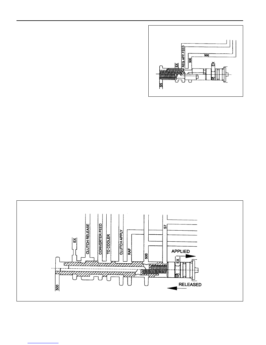
Converter Clutch Control Valve
The converter clutch control valve (refer figure 3.21) is a two position valve which applies or releases the converter
clutch.
The switching of this valve is governed by the signal pressure from S7.
When the valve is in the off or released position, converter feed oil from the PRV is directed to the release side of the
converter clutch. After flowing through the converter, oil returns to the converter clutch control valve and is then
directed to the oil cooler.
When the valve is in the on or applied position, regulated oil from the converter clutch regulator valve is directed to
the apply side of the converter clutch. This oil remains within the converter because the converter clutch piston is
sealed against the flat friction surface of the converter cover. To provide oil flow to the cooler the converter clutch
control valve directs converter feed oil from the PRV directly to the cooler circuit.
Figure 3.21- Converter Clutch Control Valve
Figure 3.20 - Converter Clutch Regulator Valve