Daewoo Musso. Manual - part 177


  Index      Daewoo     Daewoo Musso - service repair manual


Search            


Content   ..  175  176  177  178   ..


Daewoo Musso. Manual - part 177


1F2-68  M161 ENGINE CONTROLS

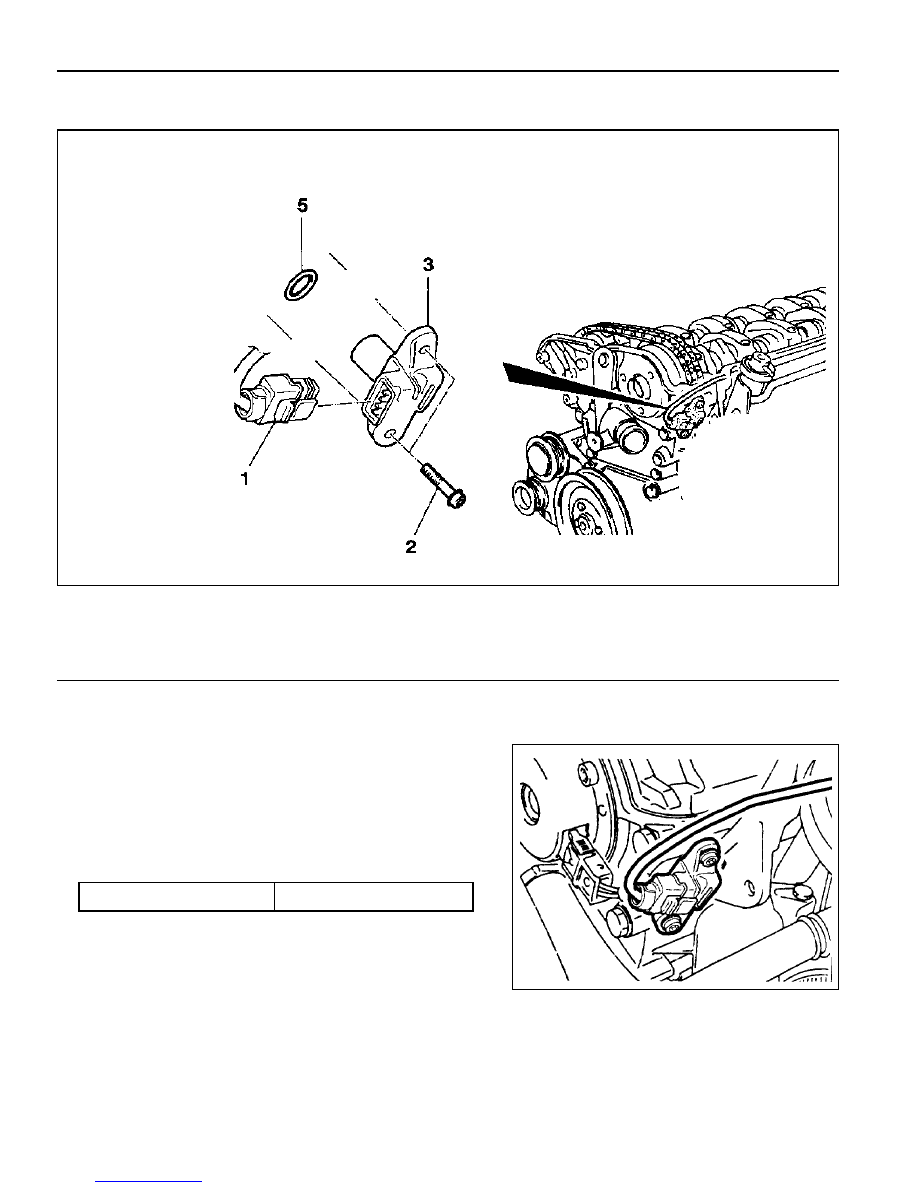
CAMSHAFT POSITION SENSOR

1 Bolt (M6 X 14) ......................................... 9-11Nm
2 Camshaft Position Sensor

Removal & Installation Procedure

1. Disconnect the wiring connector from the camshaft position

sensor.

2. Unscrew the bolt (2) and remove the camshaft position

sensor.

Installation Notice

3 Shim
5 O-ring

Tightening  Torque

9 - 11 Nm

3. Check the clearance and replace the shim if necessary.

4. Check the O-ring for damage and replace it if necessary.

5. Installation should follow the removal procedure in the

reverse order.

M161 ENGINE CONTROLS  1F2-69

Camshaft Position Sensor Power Supply
Inspection

1. Turn the ignition switch to 'ON' position.

2. Disconnect the camshaft position sensor connector.

3. Measure the voltage between the No.1 and No.3 pin of

camshaft position sensor while the ignition switch is in "ON"
position.

Notice

If the measured value is not within the specified value, check
the cable.

Notice

The signal voltage will be changed in the range of 1.2~1.7V.

Camshaft Position Sensor Output Wave
Inspection

1. Connect the test box to the ECU.

2. Measure the output wave between the ECU terminal No.104

and No.106 using the scanner or the oscilloscope while the
engine speed is at idle.

Notice

Replace the camshaft position sensor if cannot get the
output wave as shown in the figure.

Specified Value

11 - 14 V

Specified Value

1.2 - 1.7 V

Camshaft Position Sensor Signal Voltage
Inspection

1. Connect the test box to the ECU.

2. Measure the voltage between the ECU terminal No.11 and

No.106 while the engine speed is at idle.

1F2-70  M161 ENGINE CONTROLS

HOT FILM AIR MASS (HFM) SENSOR

1 Housing
2 Protector Net
3 Electronic Housing

Removal & Installation Procedure

1. Turn the HFM sensor coupling in the direction shown in the

figure in the right so that it gets separated from the contact
surface.

Notice

Make sure the HFM sensor coupling connects completely
with the contact surface Installation.

2. Remove the clip with a screw driver.

3. Pry off two tensioning clamps.

4. Remove the HFM sensor.

5. Installation should follow the removal procedure in the

reverse order.

4 Connector
5 Hot film Sensor
6 Measuring Port

M161 ENGINE CONTROLS  1F2-71

Circuit Diagram

1 Housing
2 Electronic Housing
3 Connector

R

H

 : Heat Resistance

R

T

 : Temperature Resistance

R

S

 : Sensor Resistance


Content   ..  175  176  177  178   ..