Daewoo Musso. Manual - part 171
1F2-44 M161 ENGINE CONTROLS
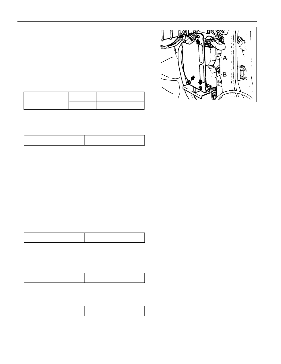
Removal & Installation Procedure
·
·
·
·
·
When removing the ECU only
1. Turn the ignition switch to "OFF" position.
2. Disconnect the negative battery cable.
3. Disconnect the couplings from ECU.
4. Unscrew the left and right bolt (3) on bolt (1) and auxiliarly
bracket and remove the auxiliarly bracket from the bracket
assembly (2).
Installation Notice
5. Unscrew the four bolts (5) and disconnect the ECU (6) from
the bracket assenbly.
Installation Notice
6. Installation should follow the removal procedure in the
reverse order.
Tightening Torque
6 - 8 Nm
5 - 7 Nm
(1)
(3)
Tightening Torque
5 - 7 Nm
8. Unscrew the bolts (5) and disconnect the ECU (6) from the
bracket assenbly.
Installation Notice
·
·
·
·
·
When Removing the ECU with ABS or ABS/ASR Unit
1. Turn the ignition switch to "OFF" position.
2. Disconnect the negative battery cable.
3. Disconnect the couplings from ECU.
4. Disconnect the coupling from ABS or ABS/ASR unit.
5. Unscrew the bolt (1) and the left and right flange nuts.
6. Remove the ECU with ABS or ABS/ASR unit assembly.
7. Unscrew the left and right bolt (3) on the auxiliary bracket
and remove the auxiliary bracket from the bracket assembly.
Installation Notice
Tightening Torque
6 - 8 Nm
Tightening Torque
5 - 7 Nm
Tightening Torque
5 - 7 Nm
9. Installation should follow the removal procedure in the
reverse order.