Daewoo Musso. Manual - part 168


  Index      Daewoo     Daewoo Musso - service repair manual


Search            


Content   ..  166  167  168  169   ..


Daewoo Musso. Manual - part 168


1F2-32  M161 ENGINE CONTROLS
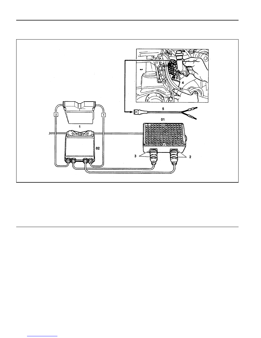
INJECTOR TEST

1 ECU
2 Test Coupling(No.1-60)
3 Test Coupling(No.61-120)
4 Measuring Beaker
5 Shop Made Cable

Preparation

03 Test Box
04 ECU Test Cable

Connection of the Equipment

1. Connect the test box to the ECU as shown in the figure.

2. Remove the 2-pin coupling from injector.

3. Remove the fuel distributor and injector with a unit. At this

time, do not remove the supply and return line.

4. Connect the shop made cable to the injector with a firing

order.

5. Collect the fuel from injector.

Tools Required

129 589 00 21 00  Test Box

210 589 08 63 00  ECU Test Cable

M161 ENGINE CONTROLS  1F2-33

Figure 8. Shop Made Cable

Figure 9. Fuel Injector Normal Spary Pattern

Failure

code

Item

Checking method

Test

step

Requirement

Specified

value

Possible cause

There should

be no leaks

and later

drops from

the injector

·

·

·

·

·

 Injector:

- Leakage

test

·

 Ignition:ON

- Remove the fuel

distributor and fuel

injector with a unit.

Þ 

1.0

·


Þ 

2.0

·

 Injector

The spray

pattern of the

injector most

show in the

figure 10

·

 Ignition:ON

- Connect the shop

made cable to the

injector.

- Collect the

spraying fuel with a

beaker

- Connect the shop

made cable to

No.11(+) and No.5

  (-) terminal in test

box.

Þ 

2.0

·

 Injector

5

33

·

·

·

·

·

 Injector:

- Function

test and

spray

pattern

check

5

33

1F2-34  M161 ENGINE CONTROLS

MAINTENANCE AND REPAIR

ON-VEHICLE SERVICE

ECU

Appearance

1 Cover
2 Plate
3 Connector
4 Flat pin

Vehicle side : number 1 - 12
Engine side : number 61 - 72

5 Pin

Vehicle side : number 13 - 60
Engine side : number 73 - 120

A Vehicle Connector : Black
B Engine Connector : Gray

M161 ENGINE CONTROLS  1F2-35

Location

Engine ECU is located at the inside of cowl side trim in right
bottom of instrument panel of passenger side.

Removal & Installation Procedure

1. Turn the ignition switch to "OFF" position.

2. Disconnect the battery negative cable

3. Remove the cowl side trim form passenger side.

4. Unscrew four securing nuts for ECU from mounting bracket.

Installation Notice

5. Pulling out the ECU from bracket.

6. Disconnect the vehicle side coupling(B).

7. Installation should follow the removal procedure in the

reverse order.

Tightening  Torque

9 - 11 Nm


Content   ..  166  167  168  169   ..