Daewoo Musso. Manual - part 162
1F2-8 M161 ENGINE CONTROLS
Servo motor open/short
Unprogramed ECU with Immobilizer
Uncoded ECU
ECU failure(NVRAM checksum failure)
ECU failure(coding ID checksum failure)
ECU failure(coding checksum failure)
ECU failure(programing checkusm failure)
ABD input signal short(power)
ABD input signal short(GND)
Low pedal valve sensor SP1 voltage
High pedal valve sensor SP1 voltage
Low pedal valve sensor SP2 voltage
High pedal valve sensor SP2 voltage
Different pedal valve sensor signal(1,2) SP1
with SP2
Pedal valve sensor 1,2 failure
HFM sensor, and throttle position sensor failure
ECU failure(incompatible CPU)
ECU failure(CPUs communication failure)
ECU failure(CPU(2) configuration failure)
ECU failure(CPU(2) fault)
ECU failure(CPU run time failure between
CPUs)
-
-
-
-
-
-
Cam actuator short(PWR)
101
102
103
104
105
108
109
110
116
117
119
120
121
122
123
125
126
127
129
130
131
132
133
134
136
137
139
140
141
142
143
144
145
146
150
151
160
161
162
163
164
167
185
186
187
188
189
190
192
193
194
195
198
199
226
learning control failure(lean, low load)
learning control failure(rich, high load)
learning control failure(lean, high load)
Low throttle position sensor(IP1) voltage
High throttle position sensor(IP1) voltage
Low throttle position sensor(IP2) voltage
High throttle position sensor(IP2) voltage
Throttle actuator learning data fault
Throttle actuator learning control failure
Exceed fuel-cut safety time
Throttle valve return spring failure
Cruise control interruption memory failure
Throttle actuator failure
Pedal module position sensor signal failure
Defferent HFM signal with throttle potentiom-
eter
Both throttle potentiomenter(IP1 & IP2)
failure
Different IPS1 with IPS2
High permanent throttle signal deviation
Message counter fault
®
cruise control “OFF”
Vehicle speed signal failure
Vehicle speed signal failure
Cruise control lever failure
Cruise control acceleration failure
Cruise control deceleration failure
ECU failure(RAM)
ECU failure(EPROM)
Servo motor control output inter-ruption
memory failure
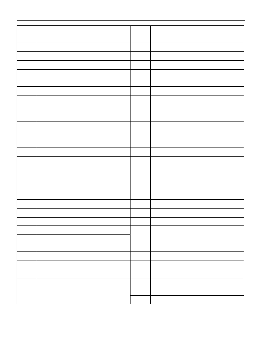
Failure
code
Description
Failure
code
Description