Daewoo Musso. Manual - part 103


  Index      Daewoo     Daewoo Musso - service repair manual


Search            


Content   ..  101  102  103  104   ..


Daewoo Musso. Manual - part 103


OM600 ENGINE MECHANICAL  1B3-119

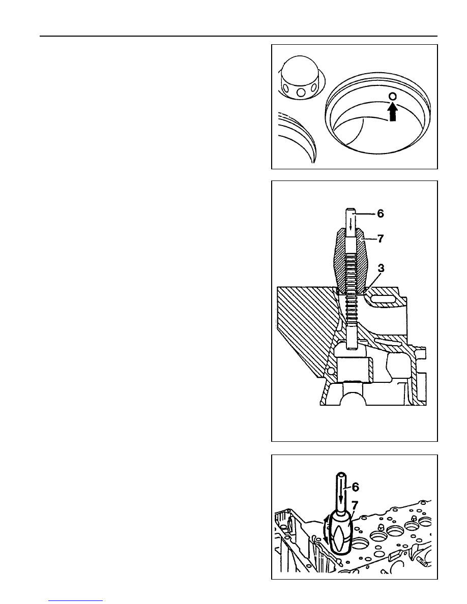
4. Reaming basic bore in cylinder head (repair size).

- Thoroughly remove carbon deposits in cylinder head.

Notice

Particularly remove the insides of the valve seat rings.

- Remove the elevation (arrow) of intake valve seat rings.

- Select correct broaching tool and guide sleeve (refer to

the table).

Notice

Before broaching work, the broaching tool must be cleared
of swarf with a stiff plastic brush.

- Lubricate the basic bore, guide sleeve and broaching tool

with petroleum.

- Push broaching tool (6) in broaching direction (arrow) into

the guide sleeve (7) far enough so that the first cut of the
broaching tool is positioned in the basic bore when guide
sleeve is fitted onto the valve seat ring (3).

6. Broaching tool

7. Guide sleeve

See the ‘standard data’

- Center the guide sleeve (7) in the valve seat ring (3) by

turning.

- Knock through the broaching tool (6) with a plastic hammer

(approx. 25g). and aluminum drift.

1B3-120  OM600 ENGINE MECHANICAL

8. Check the valve guide bore with GO / NO GO gauge (9).

The GO side (marked ‘0’) should just still drop. If the GO
side cannot be inserted, the bore of valve guide should be
reamed.

Notice

Perform the check only on cooled down cylinder head.

GO / NO GO Gauge (for Intake) 102 589 00 23 00

GO / NO GO Gauge (for Exhaust) 117 589 03 23 00

6. Cool down the new valve guide (2) with liquid nitrogen.

Notice

Do not touch the cooled valve guide by hand.

Super Cooling box 346 589 00 63 00

7. Drive in new valve guide with drift (8) until the wire ring makes

contact.

Notice

The valve guide must be driven in from the cylinder head
cover.

Drift (for Intake) 601 589 05 15 00

Drift (for Exhaust) 601 589 06 15 00

5. Heat the cylinder head (1) in a wear tank to approx. 80°C.

OM600 ENGINE MECHANICAL  1B3-121

9. If necessary, ream the valve guide bore evenly.

Notice

Never turn the reamer against the direction of rotation.

Reamer (for Exhaust)  000 589 10 53 00

Reamer (for Intake)  000 589 21 53 00

1B3-122  OM600 ENGINE MECHANICAL

VALVE SEAT RINGS

Preceding Work   : Removal of valve

Checking of valve guide, replace if necessary
Removal of prechamber

1 Cylinder Head
2 Valve Seat Ring
3 Valve Guide

A Height (Cylinder Head Upper / Lower Surface)
B Height (cylinder Head Cover Surface - Seat of

Valve Seat Ring)

D

Valve Seat Ring Outer Diameter

D1 Valve Seat Ring Inner Diameter
D2 Basic Bore Diameter
H

Height of Valve Seat Ring

Service Data

Item

D2

D

D1

H

Overlap U=D-D2

B

A

Intake

40.000 - 40.016mm

40.084 - 40.100mm

33.400 - 33.600mm

6.955 - 7.045mm

0.068 - 0.100mm

133.4mm

142.5mm

Exhaust

37.000 - 37.016mm

37.084 - 37.100mm

30.400 - 30.600mm

6.955 - 7.045mm

0.068 - 0.100mm

133.4mm

142.5mm


Content   ..  101  102  103  104   ..