Daewoo Musso. Manual - part 12


  Index      Daewoo     Daewoo Musso - service repair manual


Search            


Content   ..  10  11  12  13   ..


Daewoo Musso. Manual - part 12


GENERAL ENGINE INFORMATION  1A2-13

Leakage Test

1. Warm the engine up to normal operating temperature.

2. Disconnect the negative battery cable.

3. Remove the spark plugs.

4. Check the coolant level by opening the coolant surge tank

cap and replenish if insufficient.

5. Open the engine oil filler cap.

6. Connect the tester to air pressure line and adjust the scale

of tester.

7. Install the connecting hose to spark plug hole.

9. Connect the connecting hose to tester and measure the

leakage volume after blowing up 5bar of compressed air.

Notice

Measure the leakage volume in the completely opening
condition of throttle valve by pulling the acceleration cable.

10. Perform the pressure test according to the firing order.

Notice

Firing Order : 1 - 3 - 4 - 2

11. Compare the leakage pressure with the specifications.

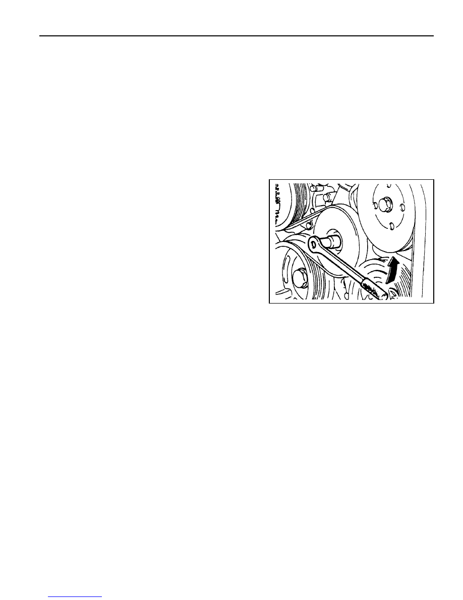
8. Position the piston of No.1 cylinder at TDC by rotating the

crankshaft.

1A2-14  GENERAL ENGINE INFORMATION

GENERAL INFORMATION

CLEANLINESS AND CARE

An automobile engine is a combination of many
machined, honed, polished and lapped surfaces with
tolerances that are measured in the ten-thousanths of
an inch. When any internal engine parts are serviced,
care and cleanliness are important. A liberal coating of
enigne oil should be applied to friction areas during
assembly, to protect and lubricate the surfaces on initial
operation. Proper cleaning and protection of machined
surfaces and friction areas is part of the repair
procedure. This is considered standard shop practice
even if not specifically stated.

Whenever valve train components are removed for
service, they should be kept in order. They should be
installed in the same locations, and with the same mating
surfaces, as when they were removed.

Battery cables should be disconnected before any major
work is performed on the engine. Failure to disconnect
cables may result in damage to wire harness or other
electrical parts.

ON-ENGINE SERVICE

Caution: Disconnect the negative battery cable be-
fore removing or installing any electrical unit, or
when a tool or equipment could easily come in con-
tact with exposed electrical terminals. Disconnect-
ing this cable will help prevent personal injury and
damage to the vehicle. The ignition must also be in
LOCK unless otherwise noted.

Notice: Any time the air cleaner is removed, the intake
opening should be covered. This will protect against
accidental entrance of foreign material, which could
follow the intake passage into the cylinder and cause
extensive damage when the engine is started.

Application

Engine Type

Displacement (CC)

Cylinder (Bore x Stroke) (mm)

Fuel Injection / Ignition System

Compression Ratio

Number of Cylinders

Camshaft Valve Arrangement

Camshaft Drive Type

Max. Output (ps/rpm)

Max. Torque (kg•m/rpm)

Firing Order

Injection Timing

Valve Timing

Intake

Open/Close

(at 2mm lift)

Exhaust Open/Close

Valve Clearance Adjustment

SECTION 1

ENGINE

SECTION 1A3(OM600 ENGINE)

GENERAL  ENGINE  INFORMATION

TABLE OF CONTENTS

Specifications . . . . . . . . . . . . . . . . . . . . . . .  1A3-1

Engine Specifications . . . . . . . . . . . . . . . . . .  1A3-1

Sectional View . . . . . . . . . . . . . . . . . . . . . .  1A3-3

OM662LA Engine . . . . . . . . . . . . . . . . . . . . .  1A3-3

OM661LA Engine . . . . . . . . . . . . . . . . . . . . .  1A3-5

Performance  Curve . . . . . . . . . . . . . . . . . .  1A3-7

OM662LA Engine . . . . . . . . . . . . . . . . . . . . .  1A3-7

OM661LA Engine . . . . . . . . . . . . . . . . . . . . .  1A3-8

Special  Tools . . . . . . . . . . . . . . . . . . . . . . .  1A3-9

SPECIFICATIONS

ENGINE SPECIFICATIONS

Special Tools Table . . . . . . . . . . . . . . . . . . . .  1A3-9

Diagnosis . . . . . . . . . . . . . . . . . . . . . . . . .  1A3-10

Oil Leak Diagnosis . . . . . . . . . . . . . . . . . . .  1A3-10

Compression Pressure Test . . . . . . . . . . . .  1A3-11

Cylinder Pressure Leakage Test. . . . . . . . .  1A3-13

General Information . . . . . . . . . . . . . . . . .  1A3-15

Cleanliness and Care . . . . . . . . . . . . . . . . .  1A3-15

On-Engine Service . . . . . . . . . . . . . . . . . . .  1A3-15

OM662LA

Four-Stroke Diesel

2874

89 x 92.4

PES 5 M55 C320 RS 168

22:1

5

SOHC

Chain-Drive

120 / 4000

25.5 / 4000

1-2-4-5-3

BTDC 18°± 10°

ATDC 11.33° / ABDC 17°

BBDC 28° / BTDC 15.25°

Automatic Control

OM661LA

Four-Stroke Diesel

2299

89 x 92.4

PES 5 M55 C320 RS 167

22:1

4

SOHC

Chain-Drive

101 / 4000

21.5 / 2400

1-3-4-2

BTDC 18°± 10°

ATDC 11.33° / ABDC 17°

BBDC 28° / BTDC 15.25°

Automatic Control

1A3-2  GENERAL ENGINE INFORMATION

OM 662 LA

720 - 820

135 - 143

8.0 - 9.5

Forced by Gear Pump

Combined Full-Flow and Partial Flow

Filter

Diesel

Application

Idle Speed (rpm)

Fuel Injection Pressure (bar)

Oil Capacity (liter)

Lubrication Type

Oil Filter Type

Fuel

ENGINE SPECIFICATIONS (Cont'd)

OM661LA

750 - 850

135 - 143

6.5 - 8.0

Forced by Gear Pump

Combined Full-Flow and Partial Flow

Filter

Diesel


Content   ..  10  11  12  13   ..