Daewoo Matiz (2003 year). Manual - part 162


  Index      Daewoo     Daewoo Matiz - service repair manual 2003 year


Search            


Content   ..  160  161  162  163   ..


Daewoo Matiz (2003 year). Manual - part 162


FIVE-SPEED MANUAL TRANSAXLE  5B – 31
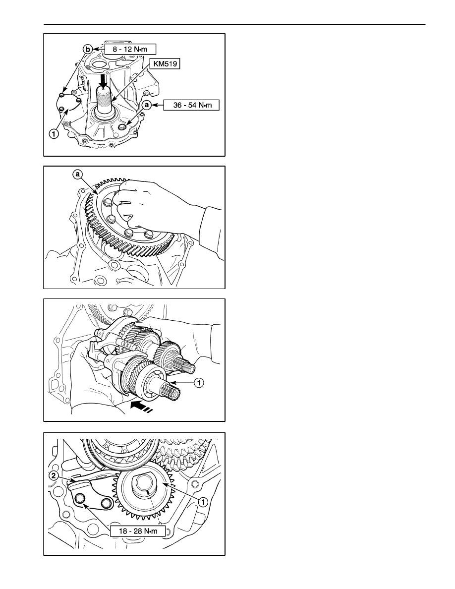
D13B727A

Tighten

Tighten the bolt to 8–12 N

S

m (71–106 lb-in).

b. Case cap retaining bolt.

D

Install the differential left side oil seal using the oil,
seal installer KM519.

D103B728

3. Install the differential assembly to the right side of

transaxle case.

a. Differential assembly.

D

When the differential ring gear surface is lower
than the right side of transaxle case surface, it is
installed correctly.

D103B729

4. Install the low and the high speed shift shaft assem-

bly to the gear unit.

5. Install the gear unit.

D

Push the gear unit by matching it with the input and
the counter shaft hole (1).

Notice: Be careful not to damage teeth of the counter
shaft pinion and the differential ring gear.

D13B730A

6. Install the fifth–reverse gear shift shaft.

7. Install the reverse idle gear shaft assembly and the

reverse gear shift lever.

D

Install the reverse idle gear shaft assembly (1).

Important: Match the marking of the reverse idle gear
shaft bolt hole with the protrusion of the transaxle case
(Right Side).

D

Install the reverse gear shift lever (2).

Tighten

Tighten the bolts to 18–28 N

S

m (13–21 lb-ft).

5B – 32  FIVE-SPEED MANUAL TRANSAXLE

D13B731A

8. Install the shift shaft ball and spring.

D

Install the third–fourth gear shift shaft ball and
spring.

Tighten

Tighten the bolt to 10–16 N

S

m (7–12 lb-ft) (a).

D

Install the fifth–reverse gear shift shaft ball and
spring.

Tighten

Tighten the bolt to 10–16 N

S

m (7–12 lb-ft) (b).

Important: Install the fifth–reverse gear shift shaft
spring marked when removing.

D13B732A

9. Install the transaxle left side case.

D

Coat the transaxle case with recommended seal-
ant.

ÁÁÁÁÁÁÁÁÁ

ÁÁÁÁÁÁÁÁÁ

Transaxle Case Sealant

ÁÁÁÁÁÁÁÁÁ

ÁÁÁÁÁÁÁÁÁ

THREE BOND 1215

D

Install the transaxle left side case to the transaxle
right side case.

Tighten

Tighten the bolts to 15–22 N

S

m (11–16 lb-ft) (a).

D

Tighten the bolts (8), stud bolts (3) if equipped with
auto clutch.

Tighten the bolts to 15–22 N

S

m (11–16 lb-ft) (b).

D13B733A

10. Install the first–second gear shift shaft ball and

spring.

Tighten

Tighten the bolt to10–16 N

S

m (7–12 lb-ft) (a).

11. Install the reverse idle gear shaft bolt.

Tighten

Tighten the bolt to 18–28 N

S

m (13–21 lb-ft) (b).

D103B734

12. Install the counter shaft bearing outer race.

D

Install the counter shaft bearing outer race using
the gear, bearing installer DW09940–53111.

a. Bearing outer race.

Important: Check if the bearing and the outer race are
correctly installed by rotating counter shaft.

FIVE-SPEED MANUAL TRANSAXLE  5B – 33

D13B735A

13. Install the counter shaft bearing shim.

D

Measure clearance between the transaxle case
surface and the bearing outer race using a
straight ruler and gauge.

D

Select shim in order that clearance is within stan-
dard.

Unit : mm (in.)

ÁÁÁÁÁÁÁÁÁÁÁ

ÁÁÁÁÁÁÁÁÁÁÁ

Measured value (A)

ÁÁÁÁÁÁÁ

ÁÁÁÁÁÁÁ

Shim thickness

ÁÁÁÁÁÁÁÁÁÁÁ

ÁÁÁÁÁÁÁÁÁÁÁ

0.33 

 0.37 (0.0130 – 0.0146)

ÁÁÁÁÁÁÁ

ÁÁÁÁÁÁÁ

0.45 (0.0177)

ÁÁÁÁÁÁÁÁÁÁÁ

ÁÁÁÁÁÁÁÁÁÁÁ

0.38 

 0.42 (0.0147 – 0.0165)

ÁÁÁÁÁÁÁ

ÁÁÁÁÁÁÁ

0.50 (0.0197)

ÁÁÁÁÁÁÁÁÁÁÁ

ÁÁÁÁÁÁÁÁÁÁÁ

0.43 

 0.47 (0.0169 – 0.0185)

ÁÁÁÁÁÁÁ

ÁÁÁÁÁÁÁ

0.55 (0.0217)

ÁÁÁÁÁÁÁÁÁÁÁ

ÁÁÁÁÁÁÁÁÁÁÁ

0.48 

 0.52 (0.0189 – 0.0205)

ÁÁÁÁÁÁÁ

ÁÁÁÁÁÁÁ

0.60 (0.0236)

ÁÁÁÁÁÁÁÁÁÁÁ

ÁÁÁÁÁÁÁÁÁÁÁ

0.53 

 0.57 (0.0209 – 0.0224)

ÁÁÁÁÁÁÁ

ÁÁÁÁÁÁÁ

0.65 (0.0256)

ÁÁÁÁÁÁÁÁÁÁÁ

ÁÁÁÁÁÁÁÁÁÁÁ

0.58 

 0.62 (0.0228 – 0.0244)

ÁÁÁÁÁÁÁ

ÁÁÁÁÁÁÁ

0.70 (0.0276)

ÁÁÁÁÁÁÁÁÁÁÁ

ÁÁÁÁÁÁÁÁÁÁÁ

0.63 

 0.67 (0.0248 – 0.0264)

ÁÁÁÁÁÁÁ

ÁÁÁÁÁÁÁ

0.75 (0.0295)

ÁÁÁÁÁÁÁÁÁÁÁ

ÁÁÁÁÁÁÁÁÁÁÁ

0.68 

− 

0.72 (0.0268 – 0.0283)

ÁÁÁÁÁÁÁ

ÁÁÁÁÁÁÁ

0.80 (0.0315)

ÁÁÁÁÁÁÁÁÁÁÁ

ÁÁÁÁÁÁÁÁÁÁÁ

0.73 

 0.77 (0.0287 – 0.0303)

ÁÁÁÁÁÁÁ

ÁÁÁÁÁÁÁ

0.85 (0.0335)

ÁÁÁÁÁÁÁÁÁÁÁ

ÁÁÁÁÁÁÁÁÁÁÁ

0.78 

 0.82 (0.0307 – 0.0323)

ÁÁÁÁÁÁÁ

ÁÁÁÁÁÁÁ

0.90 (0.0354)

ÁÁÁÁÁÁÁÁÁÁÁ

ÁÁÁÁÁÁÁÁÁÁÁ

0.83 

 0.87 (0.0327 – 0.0343)

ÁÁÁÁÁÁÁ

ÁÁÁÁÁÁÁ

0.95 (0.0374)

ÁÁÁÁÁÁÁÁÁÁÁ

ÁÁÁÁÁÁÁÁÁÁÁ

0.88 

 0.92 (0.0346 – 0.0362)

ÁÁÁÁÁÁÁ

ÁÁÁÁÁÁÁ

1.00 (0.0394)

ÁÁÁÁÁÁÁÁÁÁÁ

ÁÁÁÁÁÁÁÁÁÁÁ

0.93 

 0.97 (0.0366 – 0.0382)

ÁÁÁÁÁÁÁ

ÁÁÁÁÁÁÁ

1.05 (0.0413)

ÁÁÁÁÁÁÁÁÁÁÁ

ÁÁÁÁÁÁÁÁÁÁÁ

0.98 – 1.02 (0.0386 – 0.0402)

ÁÁÁÁÁÁÁ

ÁÁÁÁÁÁÁ

1.10 (0.0433)

ÁÁÁÁÁÁÁÁÁÁÁ

ÁÁÁÁÁÁÁÁÁÁÁ

1.03 – 1.07 (0.0406 – 0.0421)

ÁÁÁÁÁÁÁ

ÁÁÁÁÁÁÁ

1.15 (0.0453)

a. Straight ruler

b. Bearing outer race

c. Case surface

D13B736A

14. Install the side cover plate and the counter shaft fifth

gear.

D

Install the side cover plate (1).

Tighten

Tighten the screws to 6–7 N.m (53–62 lb–in).

Important: Use only new screws.

D

Install the counter shaft fifth gear (2).

Important: Position the machined boss side toward the
side cover plate.

5B – 34  FIVE-SPEED MANUAL TRANSAXLE

D13B737A

15. Install the counter shaft fifth gear nut.

D

Shift the shift yoke using a screwdriver to engage
the first–gear and the third–gear or the second–
gear and the fourth–gear (1).

Tighten

Tighten the fifth gear nut to 60–80 N

S

m (44–59 lb-ft).

D

Caulk the nut using a chisel and a hammer (2).

D103B710

16. Install the input shaft fifth gear bearing and the fifth

gear / synchronizer ring.

D

Insert the bearing into the input shaft.

D

Install the fifth gear, wave spring and synchroniz-
er ring matching synchronizer’s oil groove and in-
put shaft punched mark (1).

D103B738

17. Install the fifth gear synchronizer hub assembly.

D

Install the synchronizer springs to hub (1).

D

Install the synchronizer key (2).

Important: In case of assembling synchronizer sleeve
and hub, let A=B.

D

Position the longer boss side of hub toward inner
side (3).

D

Position the chamfered spline of sleeve toward
inner side and install the hub to the sleeve (4).

D103B739

18. Install the fifth gear fork to the synchronizer hub as-

sembly.

19. Install the fifth gear fork and the synchronizer hub

assembly to the input shaft.

Important: Position the longer boss side of hub toward
inner side and match the synchronizer key and the hub
groove with the input shaft punched mark.


Content   ..  160  161  162  163   ..