Daewoo Matiz (2003 year). Manual - part 137


  Index      Daewoo     Daewoo Matiz - service repair manual 2003 year


Search            


Content   ..  135  136  137  138   ..


Daewoo Matiz (2003 year). Manual - part 137


4E – 8  REAR DRUM BRAKES
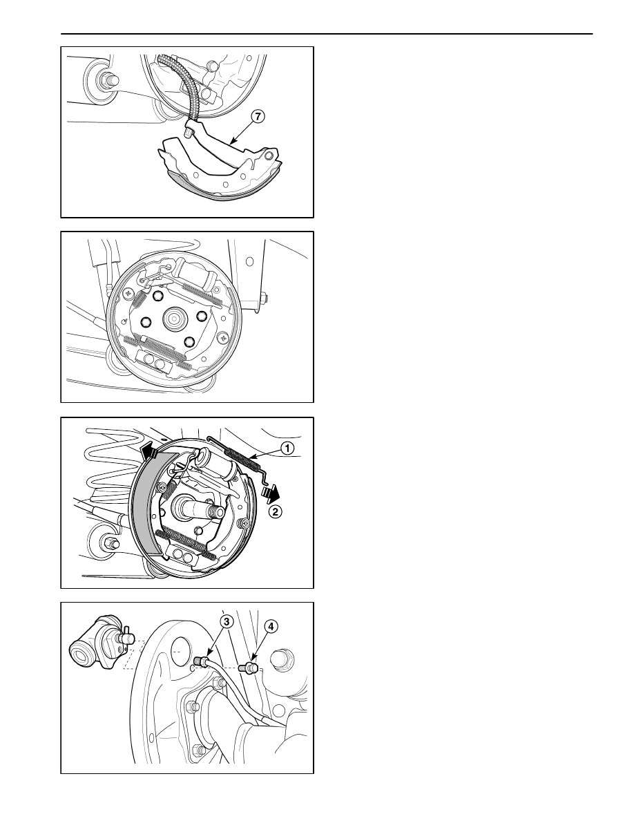
D107C508

4. Disconnect the parking brake cable from the trailing

shoe and remove the trailing shoe (7).

D107C509

Installation Procedure

1. Install in the reverse of removal.

2. Clean the adjust assembly and apply grease.

3. Connect the parking brake cable from the trailing

shoe.

4. Install the brake shoe.

5. Install the return spring.

D

Install the middle return spring and adjust lever.

D

Install the lower return spring.

D

Install the upper return spring bracket.

D

Install the upper return spring.

6. Install the brake drum. Refer to “Brake Drum” in this

section.

D107C510

WHEEL CYLINDER ASSEMBLY

Removal Procedure

1. Remove the brake drum. Refer to “Rear Brake Drum”

in this section.

2. Remove the wheel cylinder.

D

Remove the brake shoe upper spring (1).

D

Widen the leading shoe and trailing shoe (2).

D107C511

D

Disconnect the brake line fitting (3).

D

Plug the opening in the brake line to prevent fluid
loss or contamination.

D

Remove the wheel cylinder–to–backing plate bolt
(4).

REAR DRUM BRAKES  4E – 9

D17C512A

Installation Procedure

1. Install the wheel cylinder to the backing plate with the

wheel cylinder bolt (1).

Tighten

Tighten the wheel cylinder–to–backing plate bolt to 10
N

S

m (89 lb-in).

2. Connect the brake line fitting (2).

Tighten

Tighten the brake line fitting to 16 N

S

m (12 lb-ft).

3. Install the brake shoe. Refer to “Brake Shoe” in this

section.

4. Install the brake drum. Refer to “Rear Brake Drum” in

this section.

D107C513

BACKING PLATE

Removal Procedure

1. Remove the brake drum. Refer to “Rear Brake Drum”

in this section.

2. Remove the brake shoe components. Refer to “Brake

Shoe” in this section.

3. Remove the wheel cylinder assembly. Refer to “Wheel

Cylinder Assembly” in this section.

4. Remove the bolts and the backing plate.

D17C514A

Installation Procedure

1. Install the bolts and the backing plate.

Tighten

Tighten the backing plate–to–rear axle bolts to 24
N

S

m (18 lb-ft).

2. Install the wheel cylinder assembly. Refer to “Wheel

Cylinder Assembly” in this section.

3. Install the brake shoe components. Refer to “Brake

Shoe” in this section.

4. Install the brake drum.

4E – 10  REAR DRUM BRAKES

UNIT REPAIR

D107C701

WHEEL CYLINDER

Disassembly Procedure

1. Remove the wheel cylinder assembly. Refer to “Wheel

Cylinder Assembly” in this section.

2. Disassemble wheel cylinder assembly.

D

Remove the dust boots and do not reuse them (1).

D

Remove the piston (2).

D

Remove the piston cup and do not reuse it (3).

D

Remove the spring assembly (4).

D

Remove the bleeder screw (5).

3. Clean all parts with denatured alcohol. Dry the parts

with unlubricated compressed air.

D17C702A

Assembly Procedure

Important: Lubricate the new seals, the piston, the pis-
ton cup and the wheel cylinder bore with clean brake
fluid before assembly.

1. Assemble wheel cylinder assembly.

D

Insert the bleeder screw.

Tighten

Tighten the bleeder screw to 6 N

S

m (53 lb-in).

D

Install the spring and the new piston cup.

D

Install the piston and the new boots.

2. Inspect the piston for free movement.

3. Install the wheel cylinder assembly. Refer to “Wheel

Cylinder Assembly” in this section.

REAR DRUM BRAKES  4E – 11

SPECIFICATIONS

GENERAL SPECIFICATIONS

ÁÁÁÁÁÁÁÁÁÁÁÁÁÁÁÁÁÁÁ

ÁÁÁÁÁÁÁÁÁÁÁÁÁÁÁÁÁÁÁ

Application

ÁÁÁÁÁÁÁ

ÁÁÁÁÁÁÁ

Unit

ÁÁÁÁÁÁÁÁÁÁÁ

ÁÁÁÁÁÁÁÁÁÁÁ

Description

ÁÁÁÁÁÁÁÁ

ÁÁÁÁÁÁÁÁ

ÁÁÁÁÁÁÁÁÁÁÁÁ

ÁÁÁÁÁÁÁÁÁÁÁÁ

Inside Diameter

ÁÁÁÁÁÁÁ

ÁÁÁÁÁÁÁ

mm (in.)

ÁÁÁÁÁÁÁÁÁÁÁ

ÁÁÁÁÁÁÁÁÁÁÁ

180 (7.086)

ÁÁÁÁÁÁÁÁ

ÁÁÁÁÁÁÁÁ

ÁÁÁÁÁÁÁÁÁÁÁÁ

ÁÁÁÁÁÁÁÁÁÁÁÁ

Wear Limit

ÁÁÁÁÁÁÁ

ÁÁÁÁÁÁÁ

mm (in.)

ÁÁÁÁÁÁÁÁÁÁÁ

ÁÁÁÁÁÁÁÁÁÁÁ

182 (7.165)

ÁÁÁÁÁÁÁÁ

ÁÁÁÁÁÁÁÁ

Drum

ÁÁÁÁÁÁÁÁÁÁÁÁ

ÁÁÁÁÁÁÁÁÁÁÁÁ

Out of Round

ÁÁÁÁÁÁÁ

ÁÁÁÁÁÁÁ

mm (in.)

ÁÁÁÁÁÁÁÁÁÁÁ

ÁÁÁÁÁÁÁÁÁÁÁ

0.04 (0.001)

ÁÁÁÁÁÁÁÁ

ÁÁÁÁÁÁÁÁ

ÁÁÁÁÁÁÁÁÁÁÁÁ

ÁÁÁÁÁÁÁÁÁÁÁÁ

Cylindricty

ÁÁÁÁÁÁÁ

ÁÁÁÁÁÁÁ

mm (in.)

ÁÁÁÁÁÁÁÁÁÁÁ

ÁÁÁÁÁÁÁÁÁÁÁ

0.02 (0.0008)

ÁÁÁÁÁÁÁÁ

ÁÁÁÁÁÁÁÁ

ÁÁÁÁÁÁÁÁÁÁÁÁ

ÁÁÁÁÁÁÁÁÁÁÁÁ

Thickness

ÁÁÁÁÁÁÁ

ÁÁÁÁÁÁÁ

mm (in.)

ÁÁÁÁÁÁÁÁÁÁÁ

ÁÁÁÁÁÁÁÁÁÁÁ

4 (0.157)

ÁÁÁÁÁÁÁÁ

ÁÁÁÁÁÁÁÁ

Brake Lining

ÁÁÁÁÁÁÁÁÁÁÁÁ

ÁÁÁÁÁÁÁÁÁÁÁÁ

Wear Limit

ÁÁÁÁÁÁÁ

ÁÁÁÁÁÁÁ

mm (in.)

ÁÁÁÁÁÁÁÁÁÁÁ

ÁÁÁÁÁÁÁÁÁÁÁ

1 (0.039)

ÁÁÁÁÁÁÁÁ

ÁÁÁÁÁÁÁÁ

Brake Lining

ÁÁÁÁÁÁÁÁÁÁÁÁ

ÁÁÁÁÁÁÁÁÁÁÁÁ

Distance Between Lining and Drum

ÁÁÁÁÁÁÁ

ÁÁÁÁÁÁÁ

mm (in.)

ÁÁÁÁÁÁÁÁÁÁÁ

ÁÁÁÁÁÁÁÁÁÁÁ

0.3 (0.011)

ÁÁÁÁÁÁÁÁ

ÁÁÁÁÁÁÁÁ

Wheel Cylinder

ÁÁÁÁÁÁÁÁÁÁÁÁ

ÁÁÁÁÁÁÁÁÁÁÁÁ

Inside Diameter

ÁÁÁÁÁÁÁ

ÁÁÁÁÁÁÁ

mm (in.)

ÁÁÁÁÁÁÁÁÁÁÁ

ÁÁÁÁÁÁÁÁÁÁÁ

17.46 (0.687)

FASTENER TIGHTENING SPECIFICATIONS

ÁÁÁÁÁÁÁÁÁÁÁÁÁÁÁÁÁÁ

ÁÁÁÁÁÁÁÁÁÁÁÁÁÁÁÁÁÁ

Application

ÁÁÁÁÁÁÁ

ÁÁÁÁÁÁÁ

N

S

m

ÁÁÁÁÁÁ

ÁÁÁÁÁÁ

Lb-Ft

ÁÁÁÁÁÁÁ

ÁÁÁÁÁÁÁ

Lb-In

ÁÁÁÁÁÁÁÁÁÁÁÁÁÁÁÁÁÁ

ÁÁÁÁÁÁÁÁÁÁÁÁÁÁÁÁÁÁ

Castellated Nut*

ÁÁÁÁÁÁÁ

ÁÁÁÁÁÁÁ

ÁÁÁÁÁÁ

ÁÁÁÁÁÁ

ÁÁÁÁÁÁÁ

ÁÁÁÁÁÁÁ

ÁÁÁÁÁÁÁÁÁÁÁÁÁÁÁÁÁÁ

ÁÁÁÁÁÁÁÁÁÁÁÁÁÁÁÁÁÁ

Wheel Cylinder Bolt

ÁÁÁÁÁÁÁ

ÁÁÁÁÁÁÁ

10

ÁÁÁÁÁÁ

ÁÁÁÁÁÁ

ÁÁÁÁÁÁÁ

ÁÁÁÁÁÁÁ

89

ÁÁÁÁÁÁÁÁÁÁÁÁÁÁÁÁÁÁ

ÁÁÁÁÁÁÁÁÁÁÁÁÁÁÁÁÁÁ

Brake Backing Plate Bolt

ÁÁÁÁÁÁÁ

ÁÁÁÁÁÁÁ

24

ÁÁÁÁÁÁ

ÁÁÁÁÁÁ

18

ÁÁÁÁÁÁÁ

ÁÁÁÁÁÁÁ

ÁÁÁÁÁÁÁÁÁÁÁÁÁÁÁÁÁÁ

ÁÁÁÁÁÁÁÁÁÁÁÁÁÁÁÁÁÁ

Brake Pipe Fitting

ÁÁÁÁÁÁÁ

ÁÁÁÁÁÁÁ

16

ÁÁÁÁÁÁ

ÁÁÁÁÁÁ

12

ÁÁÁÁÁÁÁ

ÁÁÁÁÁÁÁ

ÁÁÁÁÁÁÁÁÁÁÁÁÁÁÁÁÁÁ

ÁÁÁÁÁÁÁÁÁÁÁÁÁÁÁÁÁÁ

Bleeder Screw

ÁÁÁÁÁÁÁ

ÁÁÁÁÁÁÁ

6

ÁÁÁÁÁÁ

ÁÁÁÁÁÁ

ÁÁÁÁÁÁÁ

ÁÁÁÁÁÁÁ

53

Q

 Castellated Nut : 25 N

S

m – 180

_

 + 2.5 N

S

m (18 lb-ft – 180

_

 + 22 lb-in.)


Content   ..  135  136  137  138   ..