Daewoo Matiz (2003 year). Manual - part 133


  Index      Daewoo     Daewoo Matiz - service repair manual 2003 year


Search            


Content   ..  131  132  133  134   ..


Daewoo Matiz (2003 year). Manual - part 133


FRONT DISC BRAKES  4D – 3
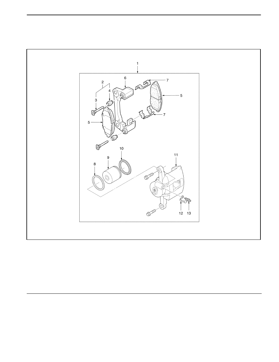
COMPONENT LOCATOR

FRONT DISC BRAKES

D17B401A

1. Front Brake Caliper Assembly
2. Front Brake Boot Assemblies
3. Pins
4. Pin Boots
5. Front Brake Pads
6. Carrier
7. Pad Spring

8. Piston Boot
9. Piston

10. Piston Seal

11. Cylinder

12. Bleeder Screw Cap
13. Bleeder Screw

4D – 4  FRONT DISC BRAKES

DIAGNOSTIC INFORMATION AND PROCEDURES

FRONT DISC BRAKE

ÁÁÁÁÁÁÁÁÁÁ

ÁÁÁÁÁÁÁÁÁÁ

ÁÁÁÁÁÁÁÁÁÁ

Condition

ÁÁÁÁÁÁÁÁÁÁÁÁÁ

ÁÁÁÁÁÁÁÁÁÁÁÁÁ

ÁÁÁÁÁÁÁÁÁÁÁÁÁ

Probable cause

ÁÁÁÁÁÁÁÁÁÁÁÁÁÁ

ÁÁÁÁÁÁÁÁÁÁÁÁÁÁ

ÁÁÁÁÁÁÁÁÁÁÁÁÁÁ

Correction

Uneven Braking

D

Inoperative carrier.

D

Replace the carrier.

D

Sticked caliper piston.

D

Repair the caliper piston or replace
the caliper assembly, if needed.

Dragging Brake

D

Sticked caliper piston.

D

Repair the caliper piston or replace
the caliper assembly if needed.

Noise and Vibration

D

Excessive rotor run out.

D

Replace the rotor.

When Brake Applied

D

Interference of the dust cover.

D

Repair the dust cover.

D

Loose caliper mounting bolts.

D

Tighten the mounting bolts.

FRONT DISC BRAKES  4D – 5

LINING INSPECTION

1. Raise and suitably support the vehicle.

2. Remove the front wheels. Refer to Section 2E, Tires

and Wheels.

3. Visually check the linings for minimum thickness and

wear.

4. Measure the thickness.

Important: The minimum thickness of the shoe and lin-
ing together is 8 mm (0.31 in.).

D107B301

5. Install the shoe and linings in axle sets only.

6. Install the front wheels. Refer to Section 2E, Tires

and Wheels.

7. Lower the vehicle.

ROTOR INSPECTION

Thickness variation can be checked by measuring the
thickness of the rotor at four or more points around the
circumference of the rotor. All measurements must be
made at the same distance in from the edge of the rotor.

If the thickness of the rotor is below 10 mm (0.40 in.),
replace the brake rotor.

During manufacturing, the brake rotor and the toler-
ances of the braking surface regarding flatness and lat-
eral runout are held very close. The maintenance of
close tolerances on the shape of the braking surfaces is
necessary to prevent brake roughness.

D107B302

In addition to these tolerances, the surface finish must
be held to a specified range. The control of the braking
surface finish is necessary to avoid pulls and erratic per-
formance and to extend lining life.

Using a commercially-available dial indicator, check lat-
eral runout as follows:

Notice: Permissible lateral runout is a maximum 0.05 mm
(0.002 in.).  If  lateral  runout  exceeds  the  specification,
ensure there is no dirt between the rotor and the hub and
that contact surfaces are smooth and free from burrs.

1. Position the transaxle in NEUTRAL.

2. Remove the rotor. Refer to “Rotor” in this section.

3. Fasten a dial indicator to the strut.

4. Set the gauge probe tip to approximately 10 mm

(0.4 in.) from the outer edge of the brake rotor, per-
pendicular to the disc and under slight preload.

5. Remove the dial indicator.

Important: Since accurate control of the rotor toler-
ances is necessary for proper performance of the disc
brakes, refinishing of the rotor should be done only with
precision equipment.

6. Refinish the rotor, if required, with precision equip-

ment. Discard the rotor if it fails to meet the above
specifications after refinishing.

7. Install the rotor. Refer to “Rotor” in this section.

D107B303

4D – 6  FRONT DISC BRAKES

REPAIR INSTRUCTIONS

ON–VEHICLE SERVICE

D107B501

SHOE AND LINING

Removal Procedure

1. Remove the front wheels. Refer to Section 2E, Tires

and Wheels.

2. Remove the brake pads.

D

Remove the pin bolt (1).

D107B502

D

Lift up the cylinder assembly (2).

D17B503A

Installation Procedure

1. Install the brake pads and the cylinder assembly with

the pin bolt.

Tighten

Tighten the pin bolt to 26 N

S

m (19 lb-ft).

2. Install the front wheels. Refer to Section 2E, Tires

and Wheels.


Content   ..  131  132  133  134   ..