Daewoo Matiz (2003 year). Manual - part 112


  Index      Daewoo     Daewoo Matiz - service repair manual 2003 year


Search            


Content   ..  110  111  112  113   ..


Daewoo Matiz (2003 year). Manual - part 112


FRONT SUSPENSION  2C – 13

D106B523

D

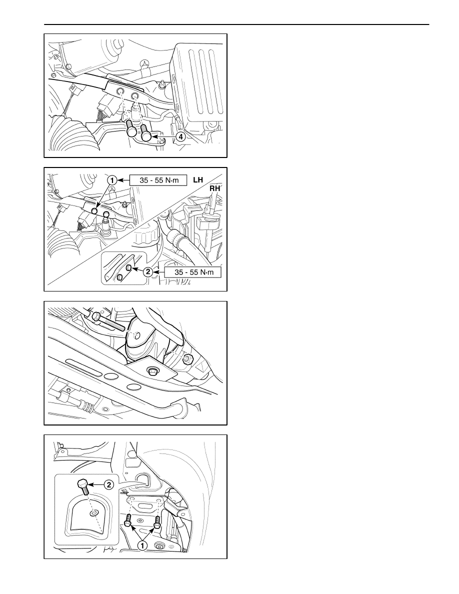
Remove the strut bar bolts at driver side (4).

Important: When removing the bolts using the tool,
do not contact the battery terminal.

D

Remove the strut bar at passenger side

D16B524B

Installation Procedure

1. Install the strut bar to the vehicle.

D

Install the strut bar at passenger side.

D

Install the strut bar bolts at driver side (1).

Important: When installing the bolts using the tool, do
not contact the battery terminal.

D

Install the strut bar bolts at passenger side (2).

D

Install the A/C low pressure pipe bracket–to–strut
bar nut.

Tighten

Tighten the strut bar bolts to 35–55 N

S

m (25–41 lb-ft).

D

Install the purge control valve to the strut bar.

D106B525

CROSSMEMBER

Removal Procedure

1. Remove the transaxle under cover. Refer to Section

5B, Five–Speed Manual Transaxle.

2. Remove the front under longitudinal frame. Refer to

“Stabilizer Shaft” in this section.

3. Remove the damping bush bolt and nut.

D106B526

4. Disconnect the power steering pressure line from the

crossmember. Refer to Section 6B, Power Steering
Pump.

5. Remove the crossmember from the vehicle.

D

Place support jack under the crossmember.

D

Remove the bumper fascia screws.

D

Remove the rear bolts (1).

D

Remove the side bolts (2).

D

Lower the support jack and remove the crossmem-
ber from the vehicle.

2C – 14  FRONT SUSPENSION

D106B527

D106B528

6. Remove the front damping bush bolts and damping

bush from the crossmember.

D16B529A

35–41 N

S

m

45–55 N

S

m

Installation Procedure

1. Install in the reverse order of removal.

2. Install the front damping bush to the crossmember.

Tighten

D

Tighten the bolts to 45–55 N

S

m (33–41 lb-ft).

a. Front damping bush bolt.

D

Tighten the bolt to 35–41 N

S

m (25–30 lb-ft).

b. Front damping bush bolt.

D16B530A

17–27 N

S

m

17–27 N

S

m

3. Install the crossmember to the vehicle with the bolts.

Tighten

Tighten the bolts to 17–27 N

S

m (13–20 lb-ft).

a. Crossmember right rear bolt.

b. Crossmember right side bolt.

FRONT SUSPENSION  2C – 15

D16B531A

17–27 N

S

m

17–27 N

S

m

c. Crossmember left rear bolt.

d. Crossmember leftt side bolt.

D16B532A

68–83 N

S

m

4. Install the front damping bush to the vehicle.

Tighten

Tighten the front damping bush bolt and nut to 68–83
N

S

m (51–61 lb-ft).

5. Install the front under longitudinal frame. Refer to

“Stabilizer Shaft” in this section.

2C – 16  FRONT SUSPENSION

UNIT REPAIR

D106B701

HUB BEARING AND KNUCKLE

Tools Required

DW 220–020A–01 Differential Bearing Puller.
DW 220–020A–04 Differential Bearing Plate Adapter.
DW 340–010

Front Wheel Hub Remover.

DW 340–020

Front Wheel Bearing Race Installer.

DW 340–030

Front Wheel Bearing Installer.

09940–71430

Front Spring Compressor.

Disassembly Procedure

1. Remove the steering knuckle assembly. Refer to

“Knuckle Assembly” in this section.

2. Remove the bolts from the wheel hub.

D106B702

3. Remove the wheel hub from the knuckle assembly

using the front wheel hub remover DW 340–010.

D

Remove the wheel hub using the front wheel hub
remover DW 340–010 (1).

D

Remove the bearing spacer (2).

D

Remove the brake rotor (3).


Content   ..  110  111  112  113   ..