Daewoo Matiz (2003 year). Manual - part 100


  Index      Daewoo     Daewoo Matiz - service repair manual 2003 year


Search            


Content   ..  98  99  100  101   ..


Daewoo Matiz (2003 year). Manual - part 100


1F – 310  ENGINE CONTROLS
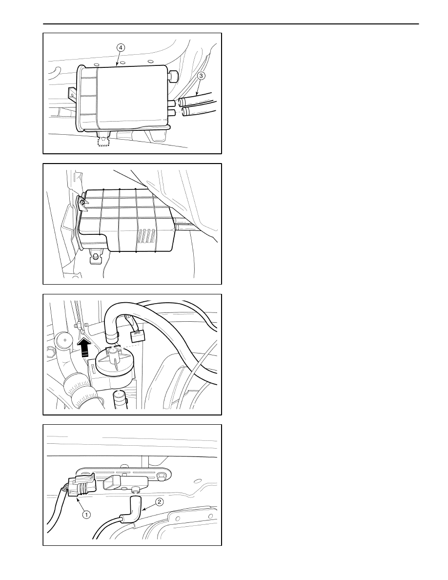
MAA1F410

D

Disconnect the canister hoses (3).

D

Remove the evaporative emission casnister (4).

MAA1F420

Installation Procedure

1. Install in the reverse order of removal.

MAA1F430

EVAPORATIVE EMISSION CANISTER
PURGE SOLENOID

1. Disconnect the negative battery cable.

2. Disconnectthe evaporative (EVAP) emission canister

purge solenoid connector.

3. Disconnect the vacuum hoses from the EVAP canis-

ter purge solenoid.

4. Unclip the EVAP emission canister purge solenoid

from the mounting bracket.

5. Installation should follow the removal procedure in

the reverse order.

MAA1F440

MANIFOLD ABSOLUTE PRESSURE
SENSOR

Removal Procedure

1. Disconnect the manifold absolute pressure (MAP)

sensor connector and vacuum hose.

D

Disconnect the MAP connector (1).

D

Disconnect the vacuum hose from the MAP sensor
(2).

ENGINE CONTROLS  1F – 311

MAA1F450

2. Remove the MAP sensor.

D

Remove the bolts (1).

D

Remove the MAP sensor with bracket (2).

MAA1F460

Installatin Procedure

1. Install in the reverse order of removal.

D

Inspect the MAP sensor vacuum hose for the tear
and damages.

2. Install the MAP sensor with the bolts and nuts.

Tighten

Tighten the MAP sensor bolts/nuts to 8–12 N

S

m

(71–106 lb-in).

Tighten the MAP sensor bracket bolt to 8–12 N

S

m

(71–106 lb-in).

D102F537

THROTTLE BODY

Removal Procedure

1. Remove the air cleaner/resonator assembly and air

intake tube. Refer to Section 1B, SOHC Engine Me-
chanical
.

2. Drain the engine coolant. Refer to Section 1D, Engine

Cooling.

D102F538

3. Disconnect the throttle cable, the throttle position

sensor and the idle air control valve connectors.

D

Open the throttle valve (1).

D

Disconnect the throttle cable (2).

D

Disconnect the idle air control valve connector (3).

D

Disconnect the throttle position sensor connector
(4).

1F – 312  ENGINE CONTROLS

D102F539

4. Disconnect the coolant hoses and vacuum hoses

from the throttle body.

D

Loosen the clamps from the coolant hoses (1).

D

Disconnect the coolant hoses from the throttle
body (2).

D

Disconnect the vacuum hoses (3).

D102F541

5. Remove the throttle body from the intake manifold.

D

Remove the throttle body bolts (1).

D

Remove the throttle body (2).

D

Discard the throttle body gasket (3).

D

Inspect the throttle body gasket for the deforma-
tion and the damages.

9–12 N

S

m

D12F542A

Installation Procedure

1. Install in the reverse order of removal.

Important: Make sure the throttle control cable do not
hold the throttle open. With the engine OFF, check to
see that the accelerator pedal is free.

2. Install the throttle body with the bolts.

Tighten

Tighten the throttle body bolts to 9–12 N

S

m (80–106

lb-in).

D12F543A

ENGINE COOLANT TEMPERATURE
(ECT) SENSOR

Removal Procedure

1. Remove the engine coolant temperature (ECT) sen-

sor. Refer to Section 1D, Engine Coolings.

ENGINE CONTROLS  1F – 313

D12F543B

Installation Procedure

1. Install the engine coolant temperature sensor.

Tighten

Tighten the engine coolant temperature sensor to
8–12 N

S

m (71–106 lb-ft).

D102F544

INTAKE AIR TEMPERATURE (IAT)
SENSOR

Removal Procedure

1. Disconnect the negative battery cable.

2. Remove the intake air temperature (IAT) sensor.

D

Disconnect the IAT sensor connector (1)

D

Disconnect the IAT sensor.

20–30 N

S

m

D12F545A

Installation Procedure

1. Install in the reverse order of removal.

2. Install the IAT sensor.

Tighten

Tighten the IAT sensor to 20–30 N

S

m (15–22 lb-ft).


Content   ..  98  99  100  101   ..