Daewoo Matiz (2003 year). Manual - part 81


  Index      Daewoo     Daewoo Matiz - service repair manual 2003 year


Search            


Content   ..  79  80  81  82   ..


Daewoo Matiz (2003 year). Manual - part 81


1F – 234  ENGINE CONTROLS

MAA1F090

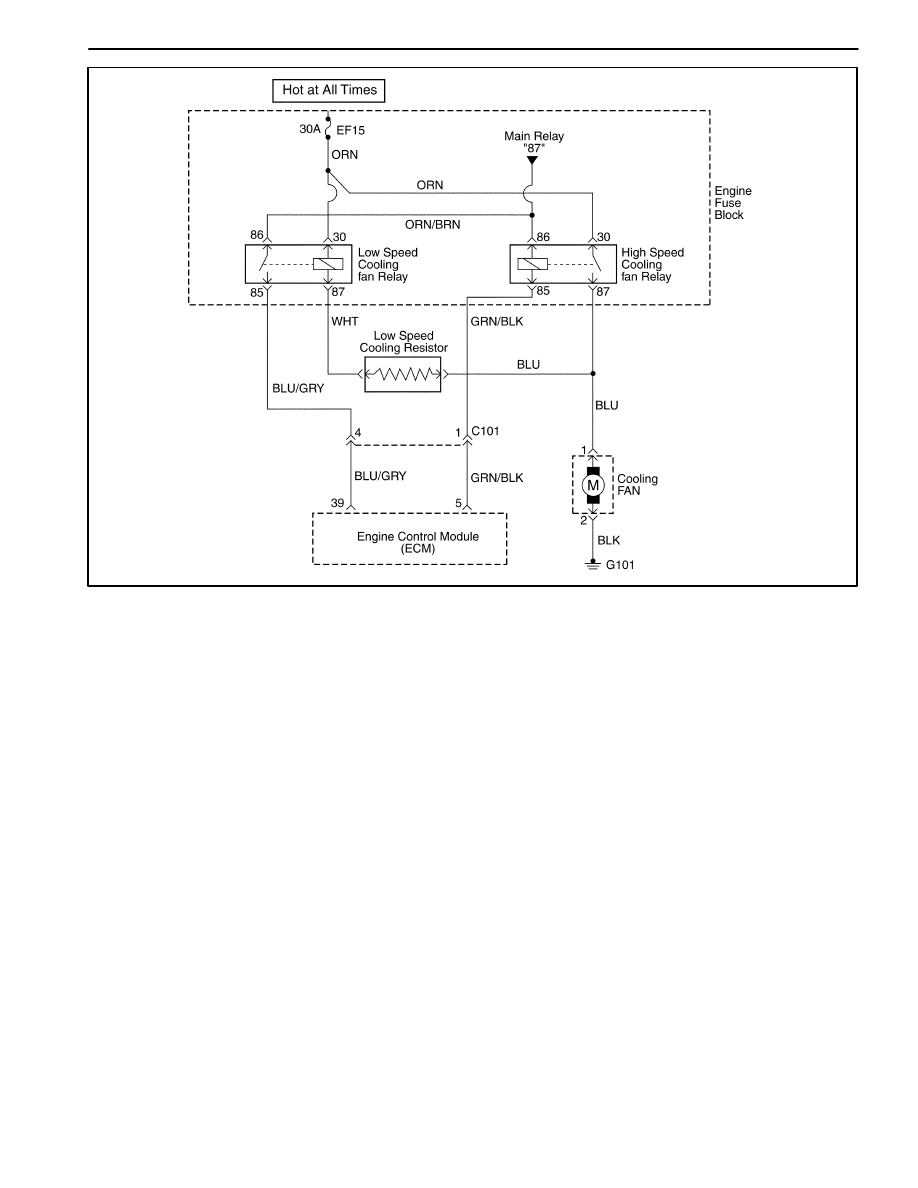
DIAGNOSTIC TROUBLE CODE (DTC) – P0481 HIGH SPEED COOLING FAN

RELAY CIRCUIT FAULT (WITHOUT A/C)

Circuit Description

Ignition voltage is supplied directly to the cooling fan
relay coil. The engine control module(ECM) controls the
relay by grounding the control circuit via an internal
switch called a driver. The primary function of the driver
is supply the ground for the component being controlled.
Each driver has a fault line which is monitored by the
ECM. When the ECM is commanding a component ON,
the voltage of the control circuit should be low (near
0volts). When the ECM is commanding the control cir-
cuit to a component OFF, the voltage potential of the cir-
cuit should be high(near battery voltage). If the fault
detection circuit senses a voltage other than what is ex-
pected, the fault line status will change causing the DTC
to set.

The relay is used to control the high current flow to the
cooling fan motors. This allows the ECM driver to only
have to handle the relatively low current used by the
relay.

Conditions for Setting the DTC

D

Diagnostic Trouble Codes (DTCs) P0117, P0118 not
set.

D

Ignition ON.

D

Ignition voltage is greater than 10 volts.

D

Engine run time is greater than 5 seconds.

Action Taken When The DTCs Sets

D

The Malfunction Indicator Lamp (MIL) will not illumi-
nate.

D

The ECM will store conditions which were present
when the DTC was set as Failure Records data only.

D

This information will not be stored in the Freeze
Frame data.

Conditions for Clearing the MIL/DTC

D

A history DTC will clear after 40 consecutive warm-up
cycles without a fault.

D

DTC(s) can be cleared by using the scan tool.

Diagnostic Aids

Using Freeze Frame and/or failure records data may aid
in locating an intermittent condition. If the DTC cannot
be duplicated, the information included in the Freeze
Frame and/or failure records data can be useful in deter-
mining how many miles since the DTC set. The fail
counter and Pass Counter can also be used to deter-
mine how many ignition cycles the diagnostics reported

ENGINE CONTROLS  1F – 235

a  Freeze  Frame  conditions  (rpm,  load,  vehicle  speed,

temperature, etc.) that .are noted. This will isolate when
the DTC failed.

DTC P0481 – High Speed Cooling Fan Relay Circuit Fault (without A/C)

Step

Action

Value(s)

Yes

No

1

Perform an Euro On-Board Diagnostic (EOBD)
System Check.
Is the system check complete?

Go to Step 2

Go to

“On-Board
Diagnostic

System Check”

2

1. Turn the ignition switch to ON with the engine

OFF.

2. Install a scan tool.
3. Command the relay ON and OFF.
Does the relay turn ON and OFF when
commanded?

Go to Step 3

Go to Step 5

3

1. Turn the ignition switch to LOCK.
2. Disconnect the engine control module (ECM)

connector.

3. Turn the ignition switch to ON.
4. Using a digital voltmeter(DVM), measure the

current in high speed relay control circuit, at
terminal 5 to ground for 2 minutes.

Does the amperage measure less than the specified
value?

0.75 amps

Go to

“Diagnostic

Aids”

Go to Step 4

4

1. Turn the ignition switch to LOCK.
2. Disconnect the relay.
3. Using a DVM, measure the resistance between

terminals 85 and 5 in the relay control circuit in
the ECM harness connector to ground.

Does the DVM display infinite resistance?

Go to Step 12

Go to Step 10

5

1. Turn the ignition switch to LOCK.
2. Disconnect the relay.
3. Connect a test light between the relay coil

terminals 86 and 85 in the relay harness
connector.

4. Turn the Turn the ignition switch to ON.
5. Using the scan tool, command the relay ON and

OFF.

Does the test light turn ON and OFF with each
commanded?

Go to Step 8

Go to Step 6

6

With the test light connected to ground, probe the
ignition feed circuit in the relay harness connector.
Does the test light illuminate?

Go to Step 7

Go to Step 11

7

1. Turn the ignition switch to LOCK.
2. Reconnect the relay.
3. Disconnect the ECM connector containing the

relay control circuit.

4. Turn the Turn the ignition switch to ON.
5. With a fused jumper wire connected to ground,

probe the relay control circuit at terminal 5 in the
ECM harness connector.

Does the relay operate?

Go to Step 9

Go to Step 10

8

Check the connections at the relay.
Is a problem found and corrected?

Go to Step 14

Go to Step 12

1F – 236  ENGINE CONTROLS

DTC P0481 – High Speed Cooling Fan Relay Circuit Fault (without A/C) (Cont’d)

Step

Action

Value(s)

Yes

No

9

Check the connection at the ECM.
Is a problem found and corrected?

Go to Step 11

Go to Step 13

10

Repair the faulty relay control circuit.
Is the repair complete?

Go to Step 14

11

Repair the faulty relay ignition feed circuit.
Is the repair complete?

Go to Step 14

12

Replace the relay.
Is the replacement complete?

Go to Step 14

13

Replace the ECM.
Is the replacement complete?

Go to Step 14

14

1. Using the scan tool, clear the Diagnostic Trouble

Codes (DTCs).

2. Start the engine and idle at normal operating

temperature.

3. Operate the vehicle within the conditions for

setting the DTC as specifiec in the supporting
text.

Does the scan tool indicate that this diagnostic ran
and passed?

Go to Step 15

Go to Step 2

15

Check if any additional DTCs are set.
Are any DTCs displayed that have not been
diagnosed?

Go to

Applicable DTC

table

System OK

ENGINE CONTROLS  1F – 237

BLANK


Content   ..  79  80  81  82   ..