Daewoo Matiz (2003 year). Manual - part 37


  Index      Daewoo     Daewoo Matiz - service repair manual 2003 year


Search            


Content   ..  35  36  37  38   ..


Daewoo Matiz (2003 year). Manual - part 37


1F – 58  ENGINE CONTROLS

MAA1F060

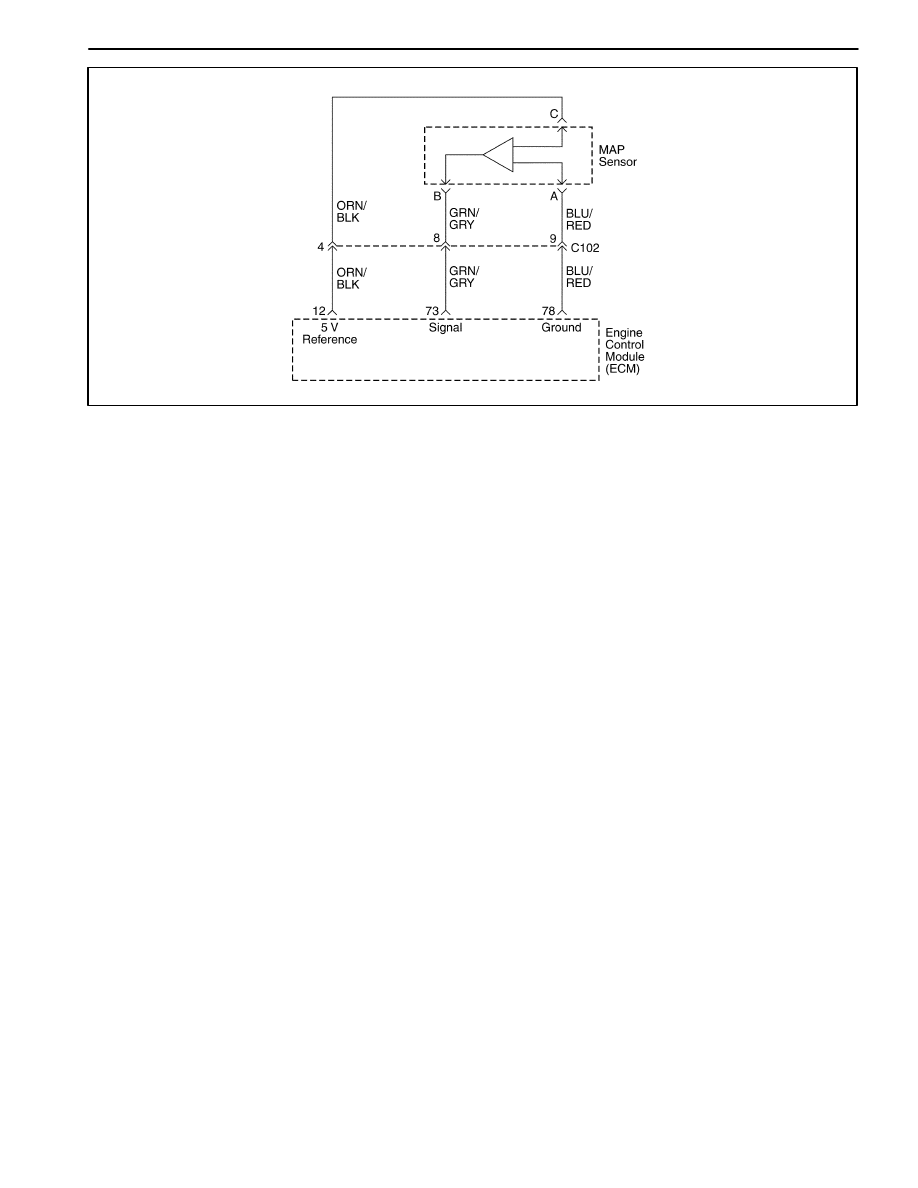
DIAGNOSTIC TROUBLE CODE (DTC) – P0107

MANIFOLD ABSOLUTE PRESSURE SENSOR LOW VOLTAGE

Circuit Description

The engine control module (ECM) uses the Manifold Ab-
solute Pressure (MAP) sensor to control the fuel deliv-
ery and the ignition timing. The MAP sensor measures
the changes in the intake manifold pressure, which re-
sults from engine load (intake manifold vacuum) and the
rpm changes; and converts these into voltage outputs.
The ECM sends a 5 volt-reference voltage to the MAP
sensor. As the manifold pressure changes, the output
voltage of the MAP sensor also changes. By monitoring
the MAP sensor output voltage, the ECM knows the
manifold pressure. A low-pressure (low voltage) output
voltage will be about 1.0 to 1.5 volts at idle, while higher
pressure (high voltage) output voltage will be about 4.5
to 5.0 at wide open throttle (WOT). The MAP sensor is
metric pressure, allowing the ECM to make adjustments
for different altitudes.

Conditions for Setting the DTC

D

This DTC can be stored in “key-on” status.

(Case A)

D

When the engine idling.

D

No throttle position(TP) sensor fail conditions pres-
ent.

D

Engine speed(rpm) is less than 2,500rpm.

D

The MAP is less than 15kPA.

(Case A)

D

When the engine part load.

D

The engine revolution speed is less than 4,000rpm.

D

No Throttle Position (TP) Sensor fails conditions
present.

D

The Throttle Position (TP) angle greather than 20.0

D

The MAP is less than 15 kPA.

An open or low voltage condition exists.

Action Taken when the DTC Sets

D

The Malfunction Indicator Lamp (MIL) will illuminate.

D

The ECM will record operating conditions at the time
the diagnostic fails. This information will be stored in
the Freeze Frame and Failure Records buffers.

D

A history DTC is stored.

D

The coolant fan turns ON.

D

The ECM will substitutes a fixed MAP value and use
TP to control the fuel delivery (the scan tool will not
show defaulted)

Conditions for Clearing the MIL/DTC

D

The MIL will turn off after four consecutive ignition
cycles in which the diagnostic runs without a fault.

D

A history DTC will clear after 40 consecutive warm-up
cycles without a fault.

D

DTC(s) can be cleared by using the scan tool.

Diagnostic Aids

With the ignition ON and the engine stopped, the man-
ifold pressure is equal to atmosphere pressure and the
signal voltage will be high.

The ECM as an indication of vehicle altitude uses this
information. Comparison of this reading with a known
good vehicle with the same sensor is a good way to
check the accuracy of a suspect sensor. Readings
should be the same 

±

0.4volt.

If a DTC P 0107 is intermittent, refer to “Manifold Abso-
lute Pressure Check”
 in this Section for further diagno-
sis.

ENGINE CONTROLS  1F – 59

If the connections are OK monitor the manifold absolute
pressure (MAP) sensor signal voltage while moving re-
lated connectors and the wiring harness. If the failure is

induced, the display on the scan tool will change. This
may help to isolate the location of an intermittent mal-
function.

DTC P0107 – Manifold Absolute Pressure Sensor Low Voltage

Step

Action

Value(s)

Yes

No

1

Perform an Euro On-Board Diagnostic (EOBD)
System Check.
Is the system check complete?

Go to Step 2

Go to

“On-Board
Diagnostic

System Check”

2

1. Connect the scan tool to the data link connector

(DLC).

2. Turn the ignition switch to ON.
Does the scan tool show the manifold absolute
pressure (MAP) sensor voltage above the value
specified?

4V

Go to Step 3

Go to Step 4

3

1. Disconnect the vacuum line from the MAP

sensor.

2. Apply 88kPA (20in.of Hg) of vacuum to the MAP

sensor.

Does the scan tool show the MAP sensor voltage
within the value specified?

1.0–1.5V

Go to

“Diagnostic

Aids”

Go to Step 4

4

1. Turn the ignition switch to LOCK.
2. Disconnect the MAP sensor connector.
3. Turn the ignition switch to ON.
4. Measure the voltage between the MAP sensor

connector terminals A and C.

Does the voltage measure within the value
specified?

4.5–5.0V

Go to Step 5

Go to Step 6

5

Connect a fused jumper between the MAP sensor
connector terminals B and C.
Does the scan tool show the MAP sensor voltage
above the value specified?

4V

Go to Step 11

Go to Step 9

6

Measure the voltage between the MAP sensor
connector terminal A and ground.
Does the voltage measure within the value
specified?

4.5–5.0V

Go to Step 7

Go to Step 8

7

1. Turn the ignition switch to LOCK.
2. Check for open wires between the MAP sensor

connector terminal A and the ECM connector
terminal 78.

Is the problem found?

Go to Step 10

Go to Step 12

8

1. Turn the ignition switch to LOCK.
2. Check for an open or short to ground in the wire

between the MAP sensor connector terminal C
and the ECM connector terminal 12.

Is the problem found ?

Go to Step 10

Go to Step 12

9

1. Turn the ignition switch to LOCK.
2. Check for an open or short to ground in the wire

between the MAP sensor connector terminal B
and the ECM connector terminal 73.

Is the problem found ?

Go to Step 10

Go to Step 12

1F – 60  ENGINE CONTROLS

DTC P0107 – Manifold Absolute Pressure Sensor Low Voltage (Cont’d)

Step

Action

Value(s)

Yes

No

10

1. Repair the wire or the connector terminal as

needed.

2. Clear any DTCs from the ECM.
3. Perform the diagnostic system check.
Is the repair complete?

System OK

11

1. Replace the manifold absolute pressure sensor.
2. Clear any DTCs from the ECM.
3. Perform the diagnostic system check.
Is the replacement complete?

System OK

12

Replace the ECM.
Is the replacement complete?

Go to Step 13

Go to Step 2

13

Check if any additional DTCs are set.
Are any DTCs displaced that have not been
diagnosed?

Go to

applicable DTC

table

System OK

ENGINE CONTROLS  1F – 61

BLANK


Content   ..  35  36  37  38   ..