Daewoo Matiz (2003 year). Manual - part 22


  Index      Daewoo     Daewoo Matiz - service repair manual 2003 year


Search            


Content   ..  20  21  22  23   ..


Daewoo Matiz (2003 year). Manual - part 22


1E – 40  ENGINE ELECTRICAL

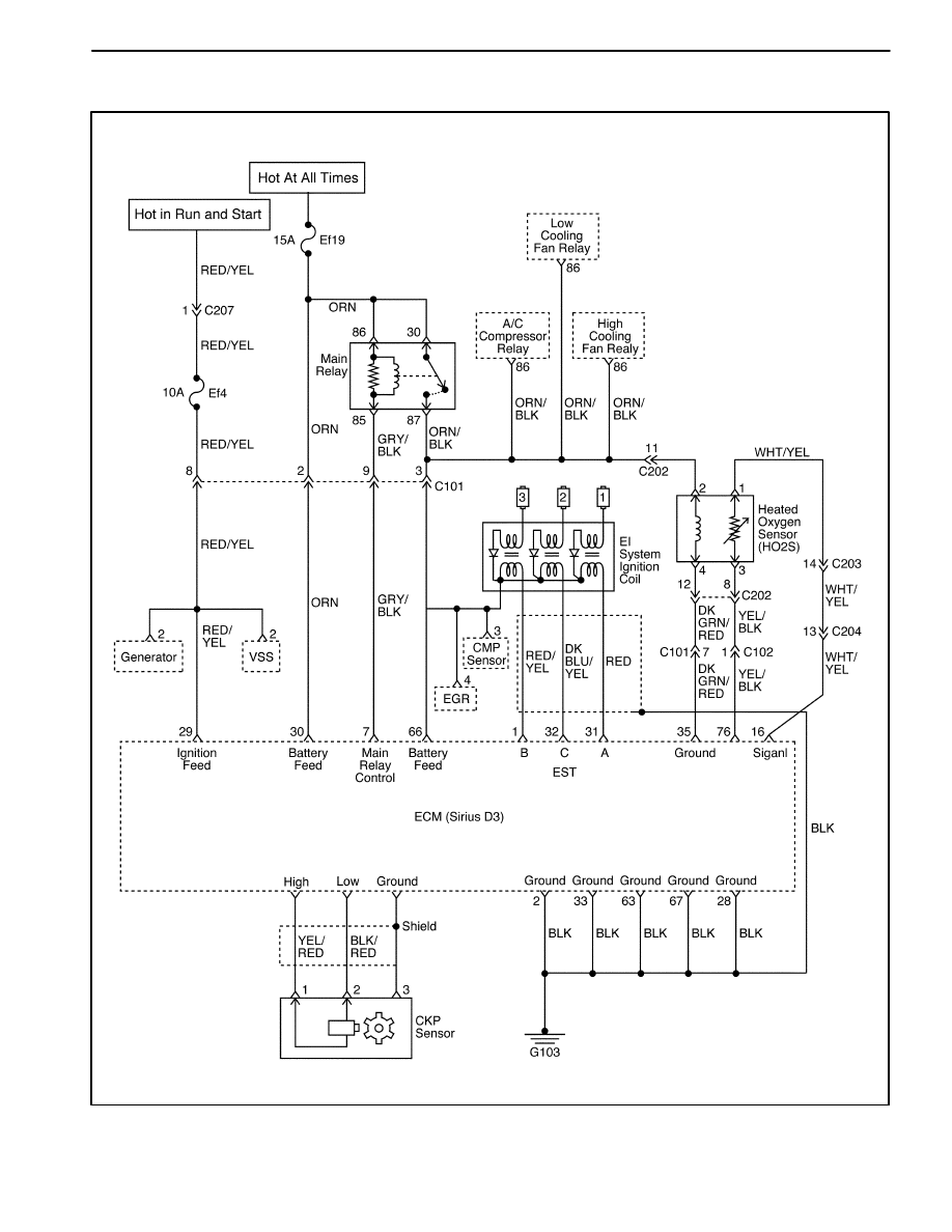
IGNITION SYSTEM CIRCUIT – EURO III

MAA1E010

ENGINE ELECTRICAL  1E – 41

SPECIFICATIONS

STARTER SPECIFICATIONS

Application

Description

Unit

Standard

Limit

Starter Motor

Type

SD 80

Output(Capacity)

kW

0.8

No Load Test @ 9 volts
Drive Pinion Speed

A

RPM

150

2,000

Brushes Length

mm (in.)

11.3–11.5

(0.445–0.453)

7.0–7.25

(0.275–0.285)

GENERATOR SPECIFICATIONS

Application

Description

Unit

Standard

Limit

Generator

Type

A-Type

J114D(MANDO)

Generator

Type

A-Type
B-Type

J114D(MANDO)

CS114D(DAC)

Regulator

A-Type

V

14.4–15.0

Regulator
Voltage

A-Type
B-Type

V

14.4–15.0

14.3–4.9

Brushes 
Length

A-Type
B-Type

mm (in.)

18.5 (0.728)
20.0 (0.787)

13.5 (0.531)

14 (0.551)

Output

A-Type

12V, 65A

Output
(Capacity)

A-Type
B-Type

12V, 65A
12V, 65A

IGNITION SYSTEM SPECIFICATIONS

Application

Description

Unit

Standard

Limit

Ignition Coil

Type

Closed
Magnetic Type

First Coil Resistance

1.2

$

10%

Second Coil Resistance

K

12.1 

$

15%

Distributor

Type

Optical Sensor
Type

Spark Plug

Type

Unlead

BPR5EY-11

RN9YC4

WR8DCX

Type

Lead

BPR5EY

RN9YC

WR8DC

Spark Plug

Gap

Unlead

mm (in.)

1.1  (0.043)

1.2  (0.047)

Lead

mm (in.)

0.8  (0.031)

Ignition Wire

Ignition Wire Resistance

K

Ω/

m

2.5–12.0

1E – 42  ENGINE ELECTRICAL

BATTERY SPECIFICATIONS

Application

Description

Unit

Standard

Limit

Battery

Type

MF

Capacity

AH

35

Cold Cranking Amps

CCA

246

FASTENER TIGHTENING SPECIFICATIONS

Application

N

S

m

Lb-Ft

Lb-In

Distributor Bolts

10–16

89–142

Battery Retainer Clamp–to–Battery Rod Nuts

6–8

53–71

Battery Carrier Tray Bolts

9–12

80–106

Battery Cable Nuts

9–12

80–106

Starter field Connector Nut

9–12

80–106

Starter Through–Bolts

4–6

35–53

Starter Mounting Bolts

55–65

41–48

Starter Solenoid Assembly Screws

6–8

53–71

Starter Solenoid Nuts

9–12

80–106

Spark Plug

20–30

15–22

Generator Through–Bolts

4–6

35–53

Generator Drive End Nut

80–110

59–81

Generator Battery Lead Connector Nut

4–7

35–62

Generator Bearing Plate Bolt

6–8

53–71

Generator Brush Holder / Rectifier Screw

9–12

80–106

Generator Belt Tension Adjusting Bolt

18–28

13–21

Generator Shackle Bracket Bolt

45–55

33–41

Generator Lower Bracket–to–Generator Bolt/Nut

18–28

13–21

Ground Bolt

35–41

26–30

Ignition Coil Screw

4–7

35–62

Ignition Coil Bracket Bolt

9–12

80–106

SECTION 1F

ENGINE CONTROLS

CAUTION: Disconnect the negative battery cable before removing or installing any electrical unit or when a
tool or equipment could easily come in contact with exposed electrical terminals. Disconnecting this cable
will help prevent personal injury and damage to the vehicle. The ignition must also be in LOCK unless
otherwise noted.

TABLE OF CONTENTS

Description and Operation

1F-4

. . . . . . . . . . . . . . . . . . 

Ignition System Operation

1F-4

. . . . . . . . . . . . . . . . . . 

Electronic Ignition System Ignition Coil

1F-4

. . . . . . . 

Crankshaft Position Sensor

1F-4

. . . . . . . . . . . . . . . . . 

Camshaft Position Sensor

1F-4

. . . . . . . . . . . . . . . . . . 

Idle Air System Operation

1F-4

. . . . . . . . . . . . . . . . . . 

Fuel Control System Operation

1F-4

. . . . . . . . . . . . . . 

Evaporative Emission Control System 

Operation

1F-5

. . . . . . . . . . . . . . . . . . . . . . . . . . . . . . 

Controlled Charcoal Canister

1F-5

. . . . . . . . . . . . . . . . 

Positive Crankcase Ventilation Control System

Operation

1F-5

. . . . . . . . . . . . . . . . . . . . . . . . . . . . . . 

Engine Coolant Temperature Sensor

1F-6

. . . . . . . . . 

Throttle Position Sensor

1F-6

. . . . . . . . . . . . . . . . . . . . 

Catalyst Monitor Oxygen Sensors

1F-6

. . . . . . . . . . . 

Electric Exhaust Gas Recirculation Valve

1F-6

. . . . . 

Intake Air Temperature Sensor

1F-7

. . . . . . . . . . . . . . 

Idle Air Control Valve

1F-7

. . . . . . . . . . . . . . . . . . . . . . 

Manifold Absolute Pressure Sensor

1F-7

. . . . . . . . . . 

Engine Control Module

1F-8

. . . . . . . . . . . . . . . . . . . . . 

Fuel Injector

1F-8

. . . . . . . . . . . . . . . . . . . . . . . . . . . . . . 

Fuel Cutoff Switch (Inertia Switch)

1F-8

. . . . . . . . . . . 

Knock Sensor

1F-8

. . . . . . . . . . . . . . . . . . . . . . . . . . . . . 

Variable Reluctance (VR) Sensor

1F-8

. . . . . . . . . . . . 

Octane Number Connector

1F-8

. . . . . . . . . . . . . . . . . 

Strategy-Based Diagnostics

1F-9

. . . . . . . . . . . . . . . . 

EOBD Serviceability Issues

1F-9

. . . . . . . . . . . . . . . . . 

Serial Data Communications

1F-10

. . . . . . . . . . . . . . . 

Euro On-Board Diagnostic (EOBD)

1F-10

. . . . . . . . . 

Comprehensive Component Monitor Diagnostic

Operation

1F-11

. . . . . . . . . . . . . . . . . . . . . . . . . . . . . 

Common EOBD Terms

1F-11

. . . . . . . . . . . . . . . . . . . . 

DTC Types

1F-13

. . . . . . . . . . . . . . . . . . . . . . . . . . . . . . 

Reading Diagnostic Trouble Codes

1F-13

. . . . . . . . . 

Primary System-Based Diagnostics 

1F-15

. . . . . . . . 

Diagnostic Information and Procedures

1F-17

. . . . 

System Diagnosis

1F-17

. . . . . . . . . . . . . . . . . . . . . . . . . . 

Diagnostic Aids

1F-17

. . . . . . . . . . . . . . . . . . . . . . . . . . 

Idle Learn Procedure

1F-17

. . . . . . . . . . . . . . . . . . . . . 

Euro On-Board Diagnostic (EOBD) System 

Check

1F-18

. . . . . . . . . . . . . . . . . . . . . . . . . . . . . . . . 

ECM Output Diagnosis

1F-20

. . . . . . . . . . . . . . . . . . . . 

Multiple ECM Information Sensor DTCs Set

1F-21

. . 

Engine Cranks But Will Not Run

1F-25

. . . . . . . . . . . . 

No Malfunction Indicator Lamp

1F-30

. . . . . . . . . . . . . 

Malfunction Indicator Lamp On Steady

1F-32

. . . . . . 

Fuel System Diagnosis

1F-34

. . . . . . . . . . . . . . . . . . . . 

Fuel Pump Relay Circuit Check

1F-36

. . . . . . . . . . . . 

Main Relay Circuit Check

1F-38

. . . . . . . . . . . . . . . . . . 

Manifold Absolute Pressure Check

1F-40

. . . . . . . . . . 

Idle Air Control System Check

1F-42

. . . . . . . . . . . . . 

Ignition System Check

1F-45

. . . . . . . . . . . . . . . . . . . . 

Engine Cooling Fan Circuit Check

1F-48

. . . . . . . . . . 

Data Link Connector Diagnosis

1F-52

. . . . . . . . . . . . . 

Fuel Injector Balance Test

1F-54

. . . . . . . . . . . . . . . . . 

Diagnostic Trouble Code Diagnosis

1F-55

. . . . . . . . 

Clearing Trouble Codes

1F-55

. . . . . . . . . . . . . . . . . . . 

Diagnostic Trouble Codes

1F-55

. . . . . . . . . . . . . . . . . 

DTC P0107 Manifold Absolute Pressure Sensor 

Low Voltage

1F-58

. . . . . . . . . . . . . . . . . . . . . . . . . . . 

DTC P0108 Manifold Pressure Sensor High 

Voltage

1F-62

. . . . . . . . . . . . . . . . . . . . . . . . . . . . . . . 

DTC P0112 Intake Air Temperature Sensor Low 

Voltage

1F-66

. . . . . . . . . . . . . . . . . . . . . . . . . . . . . . . 

DTC P0113 Intake Air Temperature Sensor High 

Voltage

1F-68

. . . . . . . . . . . . . . . . . . . . . . . . . . . . . . . 

DTC P0117 Engine Coolant Temperature Sensor 

Low Voltage

1F-72

. . . . . . . . . . . . . . . . . . . . . . . . . . . 

DTC P0118 Engine Coolant Temperature Sensor 

High Voltage

1F-74

. . . . . . . . . . . . . . . . . . . . . . . . . . . 


Content   ..  20  21  22  23   ..