Daewoo Matiz (2003 year). Manual - part 6


  Index      Daewoo     Daewoo Matiz - service repair manual 2003 year


Search            


Content   ..  4  5  6  7   ..


Daewoo Matiz (2003 year). Manual - part 6


SOHC ENGINE MECANICAL  1B – 7

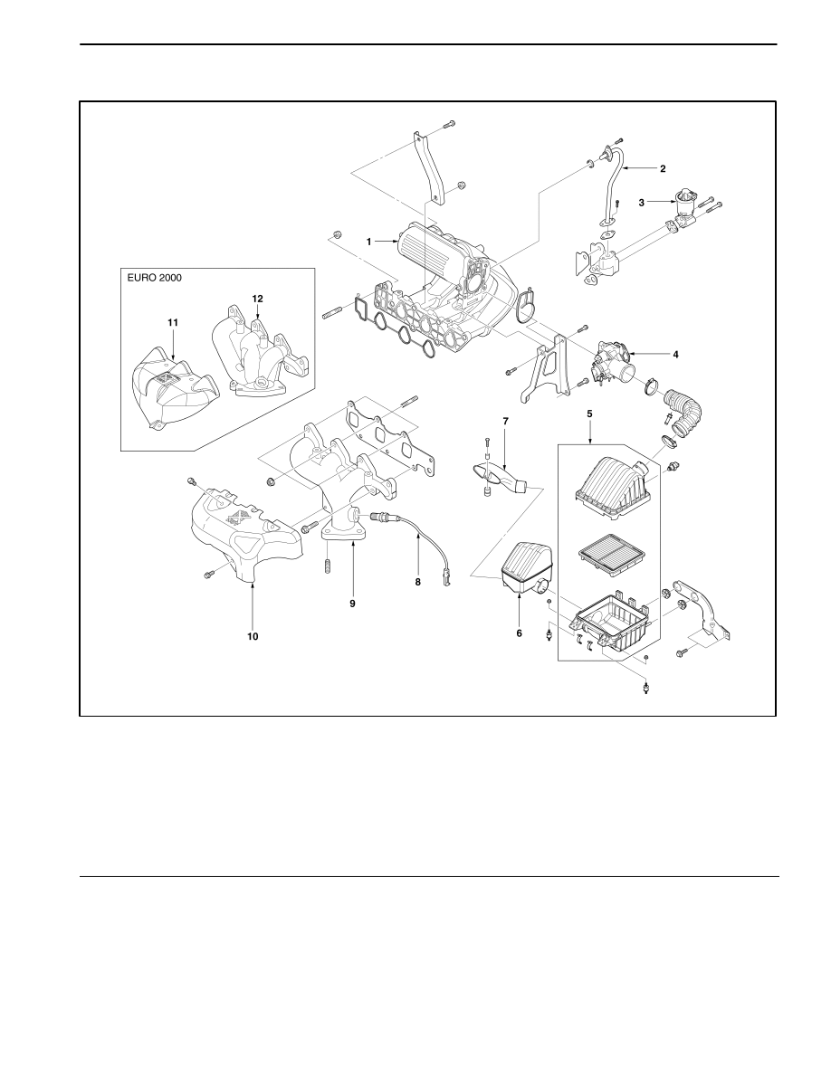
MANIFOLD & AIR FLOW SYSTEM

D21B0021

1 Intake Manifold
2 Exhaust Gas Recirculation (EGR) Pipe
3 Exhaust Gas Recirculation (EGR) Valve and

Solenoid

4 Throttle Body Assembly
5 Air Filter Assembly
6 Resonator

7 Snorkel
8 Oxygen Sensor
9 Exhaust Manifold

10 Exhaust Manifold Heat Shield

11 Exhaust Manifold Heat Shield (Euro III)

12 Exhaust Manifold (Euro III)

1B – 8  SOHC ENGINE MECANICAL

TIMING BELT & ENGINE MOUNT

D12B4041

1 Engine Mount Damping Block
2 Engine Mount Intermediate Bracket
3 Engine Mount Brace Bracket
4 Transaxle Mount Bracket
5 Transaxle Mount Damping Block
6 Engine Mount Front Bracket
7 Engine Mount Front Damping Bush
8 Timing Belt

9 Timing Belt Tensioner

10 Crankshaft Gear

11 Timing Belt Upper Front Cover

12 Timing Belt Lower Front Cover
13 Crankshaft Pulley
14 Engine Mount Lower Bracket
15 Engine Mount Upper Bracket

SOHC ENGINE MECANICAL  1B – 9

DIAGNOSTIC INFORMATION AND PROCEDURE

COMPRESSION PRESSURE CHECK

Tools Required

09915–64510 Compression Pressure Gauge

Check the compression pressure in the following proce-
dures:

1. Warm up the engine to the normal operating tempera-

ture (Cooling temperature : 80–90

_

C (176–194

_

F)).

2. Stop the engine and then remove the high tension

cable and the spark plug.

3. Disconnect the distributor optical sensor connector.

4. Install the compression pressure gauge 09915–64510

(a) in the hole of spark plug.

D12B301A

5. Disengage the clutch in Neutral (to lighten starting

load on engine upon cranking), and depress the ac-
celerator all the way to make the throttle fully open.

6. Crank the engine with the starting motor, and read the

highest pressure on the compression pressure gauge.

D

The difference of measured value between cylinders
is 98.06kPa (14.22 psi) and less.

D

On checking, make the connection perfectly airtight
between the hole of spark plug and compression pres-
sure gauge.

ÁÁÁÁÁÁ

ÁÁÁÁÁÁ

ÁÁÁÁ

ÁÁÁÁ

Unit

ÁÁÁÁÁ

ÁÁÁÁÁ

Standard

ÁÁÁÁÁ

ÁÁÁÁÁ

Limit

ÁÁÁÁÁÁ

ÁÁÁÁÁÁ

ÁÁÁÁÁÁ

ÁÁÁÁÁÁ

Compression

Pressure

– 400 rpm

kPa(psi)

1,225.75

(177.73)

1,176.72–

1,274.78
(170.62–

184.84)

7. After checking, remove the gauge and install the re-

moved parts.

OIL PRESSURE CHECK

Tools Required

09915–77310 Oil Pressure Gauge

Prior to check oil pressure, check the followings:

D

Check oil level and add if required.

D

Replace the discolored, deteriorated or diluted oil.

D

Check any oil leakage and repair the defective parts.

Check the compression pressure in the following proce-
dures:

1. Remove the oil pressure switch (b) from the cylinder

block.

2. Install the oil pressure gauge 09915–77310 (c) to the

mounting place of the oil pressure switch.

D12B302A

3. Start the engine and warm up to the normal operating

temperature.

4. Raise the engine speed up to 2,000rpm and then

read oil pressure.

ÁÁÁÁÁÁÁÁ

ÁÁÁÁÁÁÁÁ

Item

ÁÁÁÁ

ÁÁÁÁ

Unit

ÁÁÁÁÁÁÁ

ÁÁÁÁÁÁÁ

Standard

Oil Pressure – 2000rpm

kPa

(psi)

245.15–294.18

(35.55–42.66)

5. After checking, wrap the threads of oil pressure

switch with a seal tape and tighten it to the specified
torque 12–16 N

S

m (106–144 lb-in).

6. Start the engine and check oil pressure switch for oil

leakage.

1B – 10  SOHC ENGINE MECANICAL

ADJUSTMENT OF VALVE
CLEARANCE

Adjust the valve clearance in the following procedures:

1. Remove the air filter/resonator assembly and the

relevant parts installed on the cylinder head cover.

2. Remove the cylinder head cover hexagon bolts and

remove the cover.

3. Turn over the crankshaft to make No.1 cylinder

matched with the compression top dead center.
(When the camshaft sprocket notch (d) is aligned with
the timing belt rear cover triangle pointer (e) and the
crankshaft sprocket point (f) is aligned with the oil
pump housing point (g), the compression top dead
center is on the ignition sequence for No. 1 cylinder.)

D102B303

4. Check the valve clearance for No. 1 cylinder com-

pression top dead center.

ÁÁÁÁÁÁÁ

ÁÁÁÁÁÁÁ

ÁÁÁÁÁÁÁ

Condition

ÁÁÁÁÁ

ÁÁÁÁÁ

ÁÁÁÁÁ

Cylinder

No.

ÁÁÁ

ÁÁÁ

ÁÁÁ

1

ÁÁÁ

ÁÁÁ

ÁÁÁ

2

ÁÁÁ

ÁÁÁ

ÁÁÁ

3

ÁÁÁÁÁÁÁ

ÁÁÁÁÁÁÁ

ÁÁÁÁÁÁÁ

Compression top

Intake

f

f

ÁÁÁÁÁÁÁ

ÁÁÁÁÁÁÁ

dead center of

No.1 cylinder

Exhaust

f

f

Q


f

marks indicates the place where the valve clear-

ance can be checked and adjusted.

5. If the checking for the valve clearance of No.1 cylin-

der compression top dead center is over, position
No.1 cylinder on the exhaust top dead center as rotat-
ing the crankshaft in a 360–degree arc. (When the
camshaft sprocket point (h) is aligned with the timing
belt rear cover triangle pointer (e), the exhaust top
dead center is on the ignition sequence for No. 1 cyl-
inder.)

D102B304

6. Check the valve clearance for the No. 1 cylinder ex-

haust top dead center.

ÁÁÁÁÁÁÁ

ÁÁÁÁÁÁÁ

ÁÁÁÁÁÁÁ

Condition

ÁÁÁÁ

ÁÁÁÁ

ÁÁÁÁ

Cylinder

No.

ÁÁÁ

ÁÁÁ

ÁÁÁ

1

ÁÁÁÁ

ÁÁÁÁ

ÁÁÁÁ

2

ÁÁÁ

ÁÁÁ

ÁÁÁ

3

ÁÁÁÁÁÁÁ

ÁÁÁÁÁÁÁ

ÁÁÁÁÁÁÁ

Exhaust top dead

Intake

f

ÁÁÁÁÁÁÁ

ÁÁÁÁÁÁÁ

center of No.1

cylinder

Exhaust

f

Q


f

marks indicates the place where the valve clear-

ance can be checked and adjusted.

D

Check and adjust the valve clearance (i) using thick-
ness gauge (j).

D102B305

D102B306


Content   ..  4  5  6  7   ..