Daewoo Korando. Manual - part 254


  Index      Daewoo     Daewoo Korando - service repair manual


Search            


Content   ..  252  253  254  255   ..


Daewoo Korando. Manual - part 254


AUTOMATIC TRANSMISSION  5A-59

POWER FLOW - DRIVE 4 LOCK UP

In Drive 4 Lock Up, transmission drive is the same as for Drive 4 but with the application of the converter lock up clutch
to provide positive no-slip converter drive.

Control

Control for Drive 4 Lock Up is the same as for Drive 4 with the addition of the converter clutch circuit activated by
solenoid S7.

l

When S7 is switched On, S7 feed oil to the converter clutch control valve is switched off and allowed to exhaust

through the S7 solenoid. This allows the valve to move to the clutch engage position.

l

Regulated apply feed oil, delved from Line 500 oil at the converter clutch regulator valve, is directed by the

converter clutch control valve to the engage side of the converter clutch.

l

Converter clutch release oil is exhausted at the converter clutch control valve.

l

Converter feed oil is re-routed by the converter clutch control valve directly to the oil cooler and lubrication

circuit.

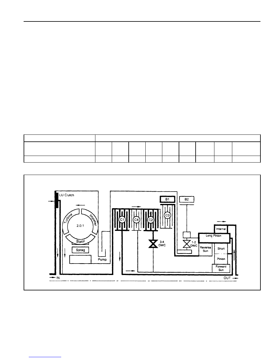
Refer to figure 5.9 arid table 5.10.

Table 5.10 - Engaged Elements - Drive 4 Lock Up

Gear State

Drive 4 Lock Up

C1

X

C2

X

C3

-

C4

-

B1

X

B2

-

1-2

OWC

-

3-4

OWC

-

LU

CLUTCH

X

ELEMENTS ENGAGED

5A-60  AUTOMATIC TRANSMISSION

DIAGNOSIS

DIAGNOSTIC SYSTEM

Recommended Test Equipment and Procedure

The test equipment is designed to be used with the control modules in all vehicles. The components used in the
transmission application are:

l

Multi Function Tester, and

l

Appropriate vehicle for testing.

Multi Function Tester (MFT)

The MFT is programmed with the special vehicle diagnostic software that allows selection of the unit under test.

The program allows the proper communication to the Transmission Control Unit (TCU).

It then requests information from the user via a menu system to select the required set up.

Examples are viewing codes, clearing error codes, and real-time operation. Set up and operation instructions are
detailed in the user manual.

This equipment can be used by trained personnel such as technicians and mechanics to diagnose electronic and
wiring problems relating to the vehicle transmission. Information that is available includes engine and road (shaft)
speed, transmission oil temperature, throttle position, solenoid/gear status and gear lever position. Current and
stored faults detected by the electronics are also available.

TCU Pin Description

The TCU pin descriptions are listed in table 6.1.1.

The wiring loom pins are shown in figure 6.1.1

Pin

No.

1

2

3

4

5

6

7

8

Identification

Common Ground

Do not use

Mode Indicator Lamp -

‘Winter’

Gear Position ‘Park’

Lamp

Gear Position ‘Reverse’

Lamp

Gear Position ‘Neutral’

Lamp

Do not use

Engine Speed Input

Sensor (-Ve)

Type

GND

-

OP

OP

OP

OP

-

IP

Description

Main power ground (or the module. Connects

directly to the battery negative terminal.

Indicates ‘WINTER’ mode shift schedule is se-

lected.

Drives the jewel in the instrument cluster to in-

dicate ‘PARK’ gear lever position.

Drives the jewel in the instrument cluster to in-

dicate ‘REVERSE’ gear lever position.

Drives the jewel in the instrument cluster to in-

dicate ‘NEUTRAL’ gear lever position.

Flywheel/Ring gear pulses to indicate engine

speed.

4WD

(Diesel)

O

O

l

l

l

l

l

4WD

(Gas)

O

O

O

l

l

l

l

l

l

Table 6.1.1 - TCU Pin Description

AUTOMATIC TRANSMISSION  5A-61

Pin

No.

  9

10

11

12

13

14

15

16

17

18

19

20

21

22

23

24

25

26

27

28

29

30

Identification

Mode Indicator Lamp -

‘Power ’

Throttle Position Sensor

Output as Pulse Width

Modulation for TOD

Air Conditioner Input Signal

Kickdown Switch

Mode Switch

Transfer Case Input

(High) -4WD Lamp High

Ignition Switch

Do not use

Gear Position ‘1’ Lamp/

Gear Position Code 1

*Gear Position ‘2’ Lamp/

Gear Position Code 2*

Gear Position ‘3’ Lamp/

Gear Position Code 3*

Gear Position ‘Drive’

Lamp/

Gear Position Code 4*

CAN (-ve)

CAN (+ve)

K-line Communication Link

Engine Speed Input

Sensor (+ve)

Road Speed Pulses

Shaft Speed Sensor

Signal

Throttle Position Sensor -

Ground

Throttle Position Sensor -

Reference

Throttle Position Sensor -

Input Signal

Transfer(or Case Input

(Low) - 4WD Lamp Low

Type

OP

OP

-

IP

IP

IP

IP

-

OP

OP

OP

OP

I/O

I/O

I/O

IP

OP

IP

GND

REF

IP

IP

Description

Indicates ‘POWER’ mode shift schedule is se-

lected.

Provides an analogue signal of the throttle po-

sition for the Torque on Demand (TOD) Con-

trol Module.

Input

Switch to indicate when a kickdown is required

at high throttle position.

Switch to select ‘NORMAL’, ‘POWER’ or ‘WIN-

TER’ shift schedule.

Voltage varies from OV to 12V.

Switch to indicate 4WD’HIGH RANGE’ is se-

lected.

Ignition power is used as the main power source

to drive the unit and the solenoids.

Drives jewel in the instrument cluster to indi-

cate

gear  leverposition’1'. Drives jewel in the instru-

ment cluster to indicate

gear  lever  position’2'. Drives jewel in the instru-

ment cluster to indicate gear lever position’3'.

Drives jewel in the instrument cluster to indi-

cate

‘DRIVE’. gear lever position.

CAN low side bus communication (CANL).

CAN high side bus communication (CANH).

Diagnostic information and vehicle coding.

Flywheel/Ring gear pulses to indicate engine

speed.

Road speed signals derived from shaft speed

sensors.

This sensor transmit shaft speed signal to the

TCU.

Throttle position sensor ground.

This is the 5V reference voltage supply gener-

ated by the unit for the throttle position sensor.

This sensor is a resistance potentiometer indi-

cating throttle position.

Voltage varies 0V to 5V.

Switch to indicate 4WD’LOW RANGE’ is se-

lected.

4WD

(Diesel)

O

O

O

O

l

l

l

4WD

(Gas)

O

O

O

O

O

O

O

O

l

l

l

l

l

l

l

l

l

l

l

l

l

l

l

l

l

l

l

l

l

l

l

l

l

l

l

l

l

5A-62  AUTOMATIC TRANSMISSION

Identification

Gear Lever Position

Transmission Oil

Temperature

Solenoid 4

Solenoid 1

Do not use

Solenoid 5

Return (-ve)

Gear Lever Position -

Ground

Transmission Oil

Temperature - Ground

Solenoid 6

Solenoid 2

Solenoid 3

Solenoid 7

Do not use

Solenoid 5 (+ve)

Type

IP

IP

OP

OP

-

IP

GND

GND

OP

OP

OP

OP

-

OP

Description

This switch has discreet values indicating the

positions selected by the gear shift lever

(PRNDL). Voltage varies 0V to 5V.

Resistive sensor indicates transmission tem-

perature .

High R = low temp

Low R = high temp

Voltage varies 0V to 5V.

On/Off solenoid normally open, combines with

other On/off solenoid 3 for shift quality and se-

quencing.

On/off solenoid normally open, combines with

other On/off solenoid to set the selected gear.

This ensures the earth path for the VPS and

the current in this line is monitored to give feed-

back control of the VPS.

PRNDL switch ground.

Ground reference for temperature sensor in-

put.

On/Off solenoid normally open, sets low/high

line pressure.

On/off solenoid normally open, combines with

other On/off solenoid to set the selected gear.

On/off  solenoid normally open, combines with

On/off solenoid 4 for shift quality and sequenc-

ing.

On/off solenoid normally open, locks up the

torque converter to Increase cruising efficiency.

This is the variable force solenoid which ramps

the pressure during gear changes and solenoid

switching, to enhance transmission shift quality.

4WD

(Diesel)

O

O

l

l

4WD

(Gas)

O

O

l

l

l

l

l

l

l

l

l

l

Pin

No.

31

32

33

34

35

36

37

38

39

40

41

42

43

44

l

l

l

l

l

l

l

l

l

l

l

l


l

= circuit connected

 O

= circuit not connected

   *

= unique

 OP = Output

  IP

= Input

 I/O

=  Input/output

GND = Ground

REF = Reference

Notice :


Content   ..  252  253  254  255   ..