DAF CF65, CF75, CF85 Series . Manual - part 396


  Index      DAF     DAF CF65, CF75, CF85 Series - service repair manual


Search            


Content   ..  394  395  396  397   ..


DAF CF65, CF75, CF85 Series . Manual - part 396


3

CF65/75/85 series

Removal and installation

AS TRONIC GEARBOX

4-3

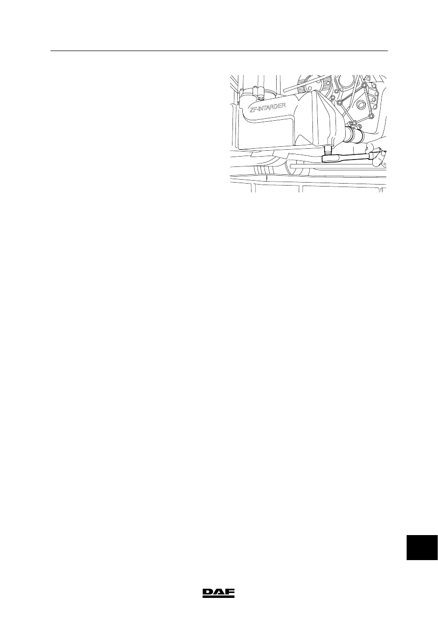
Removing the gearbox with integrated
retarder
1.

Disconnect the earth lead from the battery
terminal.

2.

Drain the engine coolant.

3.

Remove the drain plug of the intarder heat
exchanger and drain the coolant.

4.

Remove the coolant pipes from the retarder.

5.

Remove the coolant pipes between the
retarder and the engine.

6.

Disconnect the electrical connectors and
remove the air pipes from the retarder.

7.

Remove the gearbox including the retarder.

Installing the gearbox with integrated
retarder
1.

Fit the gearbox.

2.

Install the coolant pipes between the
retarder and the engine.

3.

Fit the drain plug of the intarder heat
exchanger.

4.

Connect the coolant pipes to the retarder.

5.

Connect the electrical connectors and fit the
air pipes of the retarder.

6.

Fill the cooling system.

7.

Check/fill the gearbox and integrated
retarder with oil.

ZF-INTA

RDER

V300670

14

ᓻ 200337

3

AS TRONIC GEARBOX

Removal and installation

CF65/75/85 series

4-4

4.2 REMOVAL AND INSTALLATION, GEARBOX MODULATOR

Removing the gearbox modulator
1.

Disconnect the earth lead from the battery
terminal.

2.

Remove the pressure regulator air pipe
from the gearbox modulator.

3.

Remove the gearbox.

4.

Remove the attachment bolts (2) and the
gearbox modulator (1).

Note:
When removing the gearbox modulator,
take care that the seal or parts of it does not
fall into the gearbox.

5.

Remove the seal (3) and clean the sealing
surfaces.

V300832

4

9
7
8

6

5

3

2

2

1

14

ᓻ 200337

3

CF65/75/85 series

Removal and installation

AS TRONIC GEARBOX

4-5

Installing the gearbox modulator

Seal the freed opening of the
gearbox with a clean cloth, so that
no objects can fall into the gearbox
while the selector shafts are being
adjusted.

1.

Fit the special tool (2) (DAF No. 1453138)
and secure it using the bolts (4).

CAUTION!

Always put the central selector

shaft (7) at a slant before moving it.
This means that the round bolt (9)
points either to the left or to the
right.

2.

Put the central selector shaft (7) in the
neutral position using the special tool. Align
the outer two selector shafts (6 and 8) with
the central selector shaft (7) using the
special tool.

Note:
The lever (1) must be moved twice before
the selector shafts are adjusted. To do so,
remove the pin (3) so that the lever can be
fitted in the new position.

V300830

1

4

4

6

3

2

V300831

3

6

4

4

8

7

1

2

14

ᓻ 200337

3

AS TRONIC GEARBOX

Removal and installation

CF65/75/85 series

4-6

3.

Put the central modulator control rod (4) in
neutral position; this is reached when a
slightly higher resistance is met when the
control rod is drawn out.

4.

Align the two outer control rods (3 and 5)
and the central rod.

V300692

4

5

6

2

3

1

Note:
The alignment of the control rods can be
checked with the aid of a simple tool. This tool
can be made in your own workshop. It cannot be
ordered from DAF.

25

40

240

74

212  0.1

10  0.1

14

20  0.1

9

11

15

M1

0

M1

0

60.5

2 x 45

2 x 45

fl8.7  0.1

37.5  0.1

9  

r6

64

H7

112

75

V300716

14

ᓻ 200337


Content   ..  394  395  396  397   ..