DAF LF45, LF55 Series. Manual - part 616


  Index      DAF     DAF LF45, LF55 Series - service repair manual


Search            


Content   ..  614  615  616  617   ..


DAF LF45, LF55 Series. Manual - part 616


9

LF45/55 series

General

CHASSIS

1-1

1. GENERAL

1.1 REPAIRS TO THE CHASSIS

-

Any welding, aligning, drilling and
wheelbase alteration activities that are not
described in this workshop manual or in any
of the latest releases of DAF’s Chassis
Guidelines must be authorised by DAF.

-

Following chassis repair, the cause of the
chassis damage should be rectified.

Welding
-

Chassis welding may only be carried out by
welders holding a valid EN 287-1 certificate.

-

Slag inclusions and other contamination in
the welds are totally unacceptable.

Note:
Welding a chassis made from High Tensile
Strength steel KF 450 is strongly advised
against. If, however, you do wish to weld a High
Tensile Strength steel chassis, contact DAF
always first.
The welding electrode must meet the standard:
EN 757: EY 4666 MNB.

To repair cracks in the chassis, proceed as
follows, taking account of the guidelines given
above:

1.

Remove all parts restricting a clear working
area.

2.

Thoroughly clean the crack so that the
course of the crack is clearly visible.
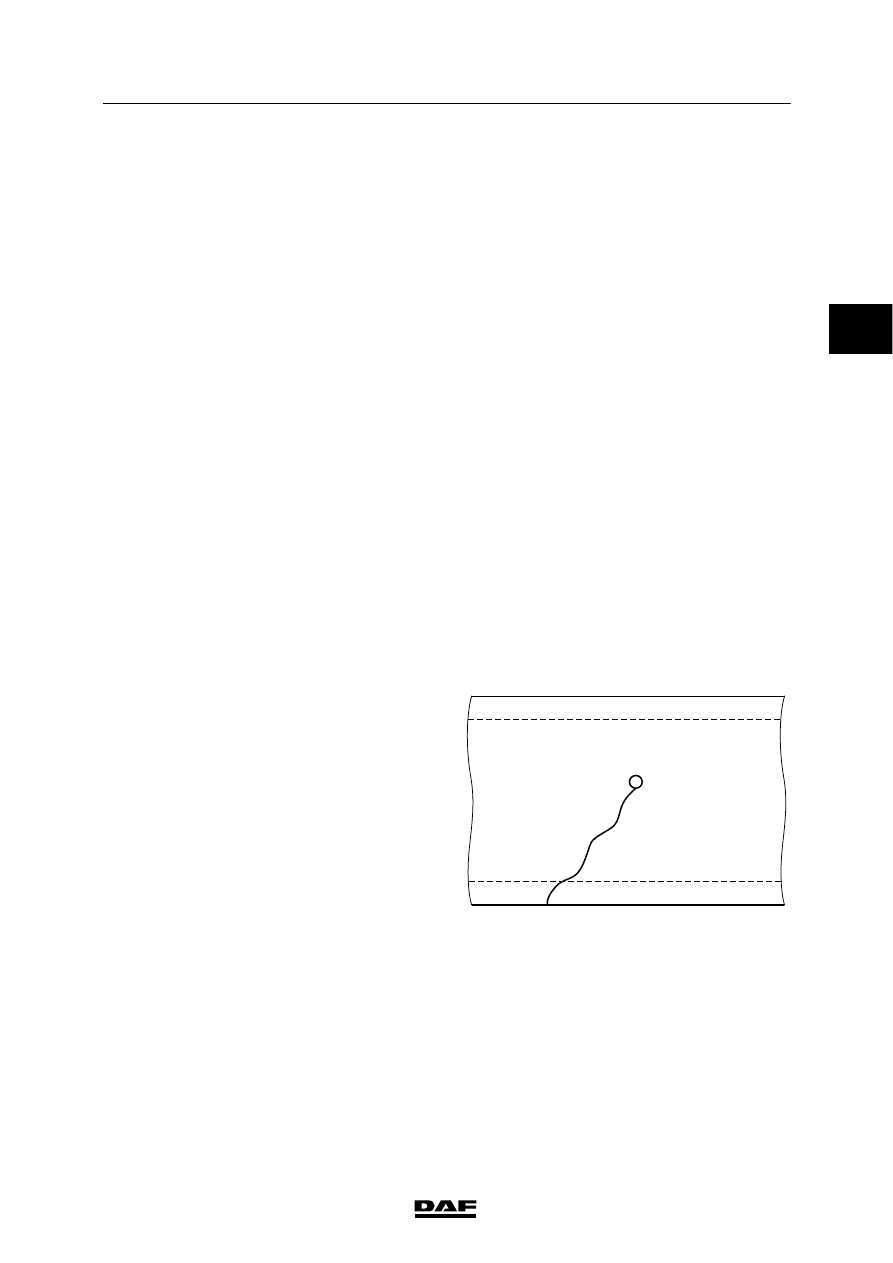
3.

Drill a small hole at the end of the crack.
This will prevent the crack from continuing.

W9 01 001

2

ǹ 0207

9

CHASSIS

General

LF45/55 series

1-2

4.

Thoroughly grind out the crack on both
sides.

5.

Take the necessary precautions to prevent
damage to electronic components. Place
the earth clamp as close as possible to the
weld and avoid bridges.

6.

Lay a bead on one side of the ground-out
crack.

7.

Gouge or grind off the material at the back
of the bead (see the arrow) so that the new
weld material is clearly visible.

8.

Finish-weld the X-seam in the usual
manner.

9.

Fill in the drilled hole.

10. Grind down the new weld so that it is flush.

Take care not to grind the chassis flange in
the process.

11. The beginning and end of a weld should not

curve inwards (see the arrow).

12. Round off the weld at the edge of the

chassis member.

W9 01 002

W9 01 003

W9 01 004

100mm

R=1

R=1

W9 01 005

2

ǹ 0207

9

LF45/55 series

General

CHASSIS

1-3

Straightening

Do not forget your own safety
during straightening operations.
When working with presses, take
care that parts cannot fly out.

The straightening of a chassis demands a high
degree of craftsmanship as in every case of
damage, an individual assessment must be
made to establish whether or not straightening
would be a sensible measure.
Deformations found after accidents will mainly
be of the following 6 types:
-

chassis is bent sideways

-

chassis has a double bend sideways
(“S-bend”)

-

chassis sags

-

chassis bulges upwards

-

chassis is twisted

-

chassis is out of square.

In many cases, the damage will be a
combination of two or more of these basic
deformations. In general, the deformations
should be dealt with in the sequence shown
above, although some combinations can be
dealt with in one straightening operation. When
deciding whether or not to straighten a chassis,
you must consider not only the degree of
chassis bending but also the angle of a bend.
If there is a sharp angular bend or fold in the
chassis, the material in that area is likely to be
severely deformed. If such a chassis were to be
realigned to its original form, there would be a
high risk of overstretching the already weakened
material and causing a crack to develop.

“Warm” straightening
DAF chassis should not be warm straightened.
Heating can cause grains in the material which
will adversely affect the material properties.

General
For every straightening operation, all stresses in
the stiffer parts of the chassis, for example in the
tandem axle attachment cross member, should
be relieved. If this is not done, these stresses
will later cause new distortions or cracks in the
chassis.

It is obvious from the above points that
straightening is a highly specialised job for which
the specialist involved bears full responsibility.
Always contact DAF when in doubt about
complicated “straightening operations”.

2

ǹ 0207

9

CHASSIS

General

LF45/55 series

1-4

1.2 DRILLING IN THE CHASSIS

Note:
There are several stress zones in a chassis.
Working on the chassis without the appropriate
knowledge (and not according to DAF
instructions) may cause irreversible damage to
the chassis. The repair shop or bodybuilder
would be held fully responsible for such work
and for any superstructure fitted.

If holes must be drilled in the chassis frame,
note the following points:

Drilling holes within a distance of 70 mm
(distance A) from a bend in the chassis is not
permitted.
-

It is on no account permitted to drill holes in
the tapered ends at the rear of a tractor
chassis.

-

Drilling holes in the flanges of the chassis
side members is not permitted.

-

The maximum diameter for drilled holes is
17 mm (dimension D in the drawing).

-

The distance between the holes, and
between the holes and the side member
flange, must be at least 3xD - with a
minimum of 30 mm (dimension B in the
drawing).

-

The distance between the lower stud hole
and the chassis underside should at least
be equal to distance C.
Distance C is

> 70 mm for a tractor

chassis.
Distance C is

> 50 mm for all other

chassis.

-

Deburr (at an angle of 45

_) and lacquer

coat the drilled hole.

Wheelbase alteration
Any alteration to the wheelbase or changes to
the rear overhang should be done in accordance
with the latest DAF Trucks Bodybuilders’
Guidelines.

Note:
When using the Bodybuilders’ Guidelines, you
are advised to first read the “General” section.

A

A

A

A

A

A

A

A

C9 00 304

B

D

B

B

C

B

C9 00 291

2

ǹ 0207


Content   ..  614  615  616  617   ..