DAF LF45, LF55 Series. Manual - part 595


  Index      DAF     DAF LF45, LF55 Series - service repair manual


Search            


Content   ..  593  594  595  596   ..


DAF LF45, LF55 Series. Manual - part 595


8

LF45/55 series

General

SINGLE REAR AXLE 10.20

2-3

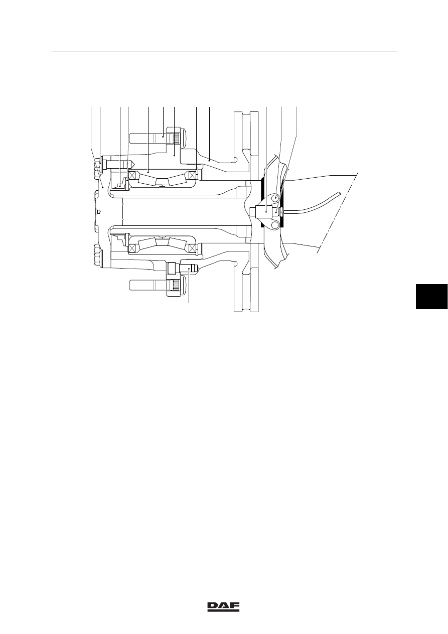
2.2 OVERVIEW DRAWING, WHEEL HUB

;;;;;;

;;;;;

;;;;;

;

;

;;;

;;;

;;;

;;

;;

;;

;;

;;;;;;;;;;

;;;;;;;;;;

;

;

;;;;

;;;;

;

;

;;

;

;

;;;;;;

;;;;;;

;;;;;

;;;;;

;;;;;

;

;;;

;;;

;;;

;;

;;

;;

;;;;;;;;;;

;;;;;;;;;;

;

;;;;

;;;;

;;;;

;;;;

;

;;

;;

;;;

;;;

;;;

;;;

;;;

;;;

;;;

;;;

;

;

A8 00 374

1 2

3 4

5

6 7

8 9

10 11 12

13

Legend
1.

Stub axle

2.

Stub axle attachment bolt

3.

Hub nut

4.

Thrust washer

5

Compact bearing

6.

Wheel stud

7.

Wheel hub

8.

Spring washer

9.

Brake disc

10. Wheel-speed sensor holder
11.

Wheel-speed sensor holder attachment
bolts

12. Wheel-speed sensor
13. Brake disc attachment bolt

6

ᓻ 200313

8

SINGLE REAR AXLE 10.20

General

LF45/55 series

2-4

6

ᓻ 200313

8

LF45/55 series

Inspection and adjustment

SINGLE REAR AXLE 10.20

3-1

3. INSPECTION AND ADJUSTMENT

3.1 INSPECTING DIFFERENTIAL OIL LEVEL

To prevent skin injury, avoid
unnecessary contact with the
drained oil.

1.

Position the vehicle on a level surface.

2.

Remove the level check/filler plug (1). The
oil level must reach the level check/filler
opening (1).

3.

Apply sealant to the plug. Secure the plug.

1

A8 00 375

3.2 CHECKING OPERATION OF DIFFERENTIAL LOCK

1.

Jack up the rear axle and support it on
stands.

2.

Bring the air system to operating pressure.

3.

Engage the differential lock. The warning
indicator in the cab should now be
activated.

4.

Check whether there is a “rigid” connection
between the driven wheels.

5.

Disengage the differential lock. The warning
indicator must no longer be activated and
the “rigid” connection between the driven
wheels should be interrupted.

6

ᓻ 200313

8

SINGLE REAR AXLE 10.20

Inspection and adjustment

LF45/55 series

3-2

3.3 INSPECTION, WHEEL-SPEED SENSOR RING

1.

Remove the wheel hub.

2.

Check the sensor ring (2) for deposits.
Special attention should be paid to deposits
between the teeth of the sensor ring.
Clean the sensor ring if necessary.

3.

Check the sensor ring (2) for damage. Even
the slightest damage may cause a failure.
If necessary, replace the wheel hub.

4.

Check the sensor (1) for smooth operation.
If necessary, clean the sensor (1) and
re-apply the specified anti-corrosion agent.
See main group “Technical data”.

Never tap the sensor with a
hammer. This may damage both the
sensor and the sensor ring.

5.

Check the ABS system for proper
operation.

A8 00 379

1

2

6

ᓻ 200313


Content   ..  593  594  595  596   ..