DAF LF45, LF55 Series. Manual - part 508


  Index      DAF     DAF LF45, LF55 Series - service repair manual


Search            


Content   ..  506  507  508  509   ..


DAF LF45, LF55 Series. Manual - part 508


7

LF45/55 series

Removal and installation

STEERING BOX

4-9

8.

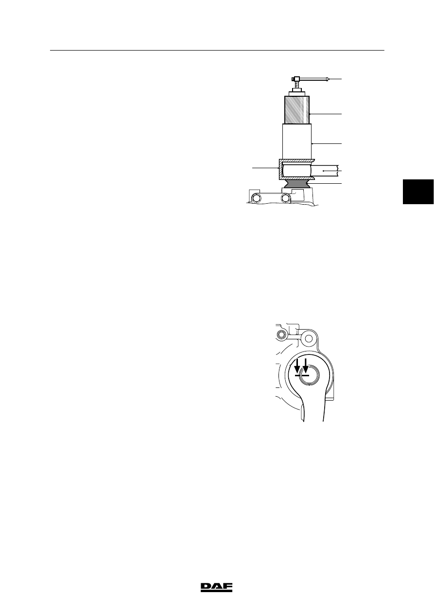
Slide the claw (A), special tool
(DAF no. 0694916), over the pitman arm
(1).
If necessary, cut off the sector shaft dust
seal (2).

9.

Slide the adapter (B) with the hydraulic
puller (C) into the claw (A).

10. Screw out the spindle (D) of the hydraulic

puller (C) as far as possible and then screw
the hydraulic puller (C) into adapter (B) as
far as possible using an open-end spanner.

11. Screw in the spindle (D) until the pitman

arm comes off the sector shaft.
If the pitman arm still has not come off after
the spindle has been completely screwed
in, screw the spindle out again and screw
the puller into the adapter (B) as far as
possible. Then screw in the spindle (D)
again until the pitman arm comes off.

C

D

B

1

2

A

S7 00 030

Installing pitman arm
1.

Fit a new dust seal on the sector shaft.

2.

Grease the surface of the dust seal that is
against the steering box using grease with a
melting point

>130_C.

The grease will protect the seals from dirt
and water.

3.

Install the pitman arm on the sector shaft so
that the marks on the pitman arm and the
sector shaft are aligned.

Note:
As the sector shaft nut normally has to be
locked in the same position, the sector shaft
nut can only be locked twice. After that, the
nut must be replaced. The nut must not be
locked in the same place again.

4.

Fit the nut on the sector shaft and tighten it
to the specified torque, see “Technical
data”.

S7 00 619

ᓻ 200322

3

7

STEERING BOX

Removal and installation

LF45/55 series

4-10

5.

Lock the sector shaft nut by tapping the
locking ring of the attachment nut at least
2.5 mm into one of the recesses of the
sector shaft.
Always use a part of the locking ring that
has not been used before.

S7 00 618

6.

Re-fit the stop bolts in their original
positions and tighten them to the specified
tightening torque, see “Technical data”.

7.

Install the steering box.

S7 00 620

ᓻ 200322

3

7

LF45/55 series

Removal and installation

STEERING BOX

4-11

4.4 REMOVAL AND INSTALLATION OF PRESSURE-LIMITING VALVE

Do not install a pressure-limiting
valve with a preset value exceeding
that of the original valve.

Removing pressure-limiting valve
1.

Remove the steering box.

2.

Clean the pressure-limiting valve and the
surrounding area.

3.

Remove the pressure-limiting valve.

Note:
The pressure-limiting valve cannot be
dismantled or adjusted.

Installing pressure-limiting valve
1.

Fit a new O-ring to the pressure-limiting
valve and install the valve in the steering
box. Tighten the valve to the specified
torque, see “Technical data”.

2.

Install the steering box.

3.

Fill and bleed the steering gear.

4.

Take a test drive. During the test drive,
check that the steering gear is functioning
properly. After the test drive, check the
steering gear for leaks.

S7 00 616

ᓻ 200322

3

7

STEERING BOX

Removal and installation

LF45/55 series

4-12

4.5 REMOVAL AND INSTALLATION OF PISTON

Note:
The activities described may only be carried out
if the steering box can be tested using a test
equipment case after the work has been carried
out.

Removing piston
1.

Clean the steering box and the surrounding
area.

2.

Place the steering gear in the central
position. This can be checked using the
marks on the steering box.

3.

If the vehicle has a steered trailing swivel
axle, take the angle sensor off the steering
box.

4.

Mark the end stops of the wheel-deflection
limiting valves and remove these.

5.

Block the rear wheels, jack up the rear axle
and support it on stands.

6.

Take the steering rod off the pitman arm.

S7 00 623

ᓻ 200322

3


Content   ..  506  507  508  509   ..