DAF LF45, LF55 Series. Manual - part 505
7
LF45/55 series
Inspection and adjustment
STEERING BOX
3-7
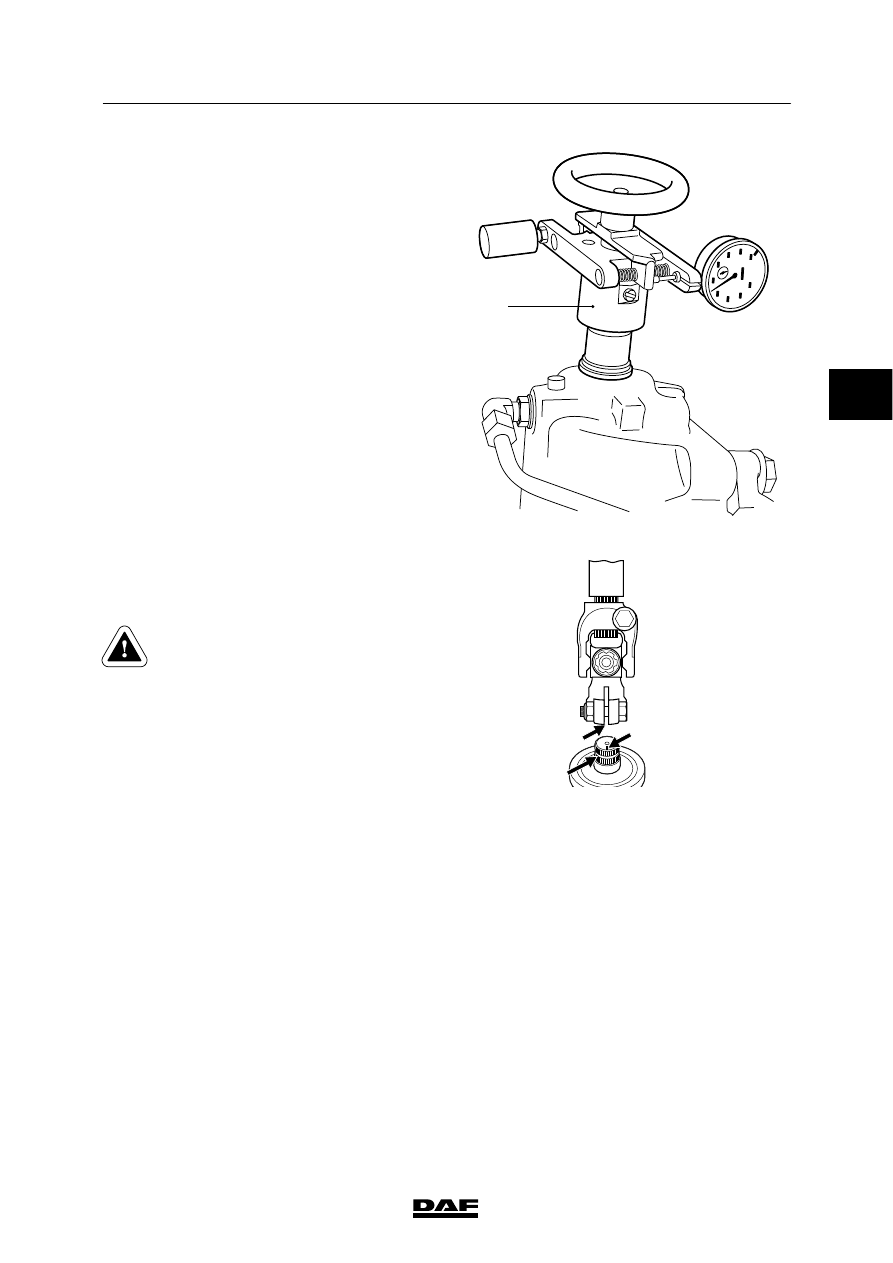
8.
Fit the resistance-torque tester (A) to the
steering box input shaft.
9.
Carefully turn the input shaft approx.
3
/
4
turn
out of the steering box central position using
the resistance-torque tester. Read off the
micrometer left and right outside the
pressure point. Check whether there is a
“heavy” point outside the pressure point.
Determine the resistance value using the
diagram with the resistance-torque tester.
10. Place the steering box in the central
position. Turn the input shaft half a turn
from the central position.
Turn the input shaft carefully past the
central position using the resistance-torque
tester and note the micrometer reading in
the pressure point. Use the diagram
supplied with the resistance-torque tester to
determine the resistance value and
compare it to the specified value, see
“Technical data”.
A
S7 00 624
11. Fit the universal joint to the steering box
input shaft. The groove (A) in the coupling
must be aligned with the mark (B) on the
steering-box input shaft.
Check that the universal joint is
correctly in place on the input shaft
so that the attachment bolt can be
fitted in the notch (C).
12. Fit a new, original attachment nut and bolt in
the universal joint.
Tighten the attachment bolt to the specified
torque, see “Technical data”.
13. Install the steering rod. Tighten the castle
nut to the specified tightening torque, see
“Technical data”.
14. Fill and bleed the steering gear.
15. Take a test drive.
S7 00 594
A
B
C
ᓻ 200322
3