DAF LF45, LF55 Series. Manual - part 486


  Index      DAF     DAF LF45, LF55 Series - service repair manual


Search            


Content   ..  484  485  486  487   ..


DAF LF45, LF55 Series. Manual - part 486


0

7

LF45/55 series

152N front axle

TECHNICAL DATA

6-3

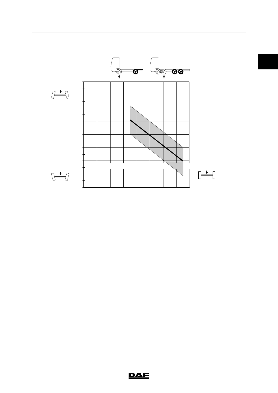
Toe, 152N front axle

1

2

3

4

5

6

7

8

0

-1

0,5

-0,5

-1,5

1,5

2,5

3,5

4,5

5,5

-2

2

3

4

5

6

1

mm/m

152 N

x 1000 KG

S7 00 414

Steering ball joints
Axial play

max. 1.5 mm

Swivel axle
Axial play

0.05 - 0.3 mm

List of shim sizes (thickness) for adjusting
swivel axle play

1.50 mm
1.75 mm
1.88 mm
2.00 mm
2.13 mm
2.25 mm
2.38 mm

ᓻ 200322

7

TECHNICAL DATA

152N front axle

LF45/55 series

6-4

Wheel offset of needle bearings
-

dimension a: 12 - 13 mm

-

dimension b: 3 - 4 mm

;;

;;

;;

;;

;;

;;;;;;

;;;;;;

;

;

;;

;;

;;

;;

;;

;;

;

;

;

;

;;;

;;;

;;;

;;;

;;;

;;;

;

;

;

;

;

;

;

;

;;;

;;;

;;;

;;;

;

;;

;;

;;

;;

;;

;;

;;

;;

;;

S7 00 710

a

b

Steering rod adjustment
The angle between the marks on the steering
box input shaft and the mark on the steering box
for adjusting the steering rod are shown in the
graph. This angle is shown with the wheels of
the front axle in the “straight ahead” position.

Explanation of graph
1.

The axle type and the axle configuration (1)
is shown at the top of the graph.

2.

The angle between the marks on the
steering box input shaft and the mark on the
steering box (2) are shown on the left-hand
side of the graph.
Note that there are two different graphs for
LHD and RHD vehicles.

3.

The front axle load (3) is shown at the
bottom of the graph.

4.

The permitted angle at any axle load is
indicated by the shaded area (4) in the
graph.

5.

If the measured value lies outside the
shaded area (4), the angle must be
adjusted to the value indicated by the
continuous line (5). Set the correct angle by
screwing the ball end of the steering rod in
or out.

7500

7050

A

B

5550

4150

3000

-20

-30

0

+10

+20

+30

-10

-19

-9

0,5

10

27

17

7

0

-10

152 N

 KG

S7 00 877

+

-

0

ᓻ 200322

0

7

LF45/55 series

152N front axle

TECHNICAL DATA

6-5

Steering rod adjustment, LHD vehicles

7500

7050

5550

4150

3000

-20

-30

0

+10

+20

+30

-10

-19

-9

0,5

10

27

17

7

0

-10

152 N

 KG

S7 00 886

+

-

Note:
“+” on the vertical axis of the graph indicates
towards the driver’s side. “--” indicates towards
the co-driver’s side.

ᓻ 200322

7

TECHNICAL DATA

152N front axle

LF45/55 series

6-6

Steering rod adjustment, RHD vehicles

7500

7050

5550

4150

3000

-20

-30

0

+10

+20

+30

-10

-19

-9

0,5

10

27

17

7

0

-10

152 N

 KG

S7 00 876

+

-

Note:
“+” on the vertical axis of the graph indicates
towards the driver’s side. “--” indicates towards
the co-driver’s side.

Steering rod arm
Abutting surface of steering rod arm to swivel
axle treated with

Loctite 2701

Wheel speed sensor ring
Axial end play

max. 0.25 mm

0

ᓻ 200322


Content   ..  484  485  486  487   ..