DAF LF45, LF55 Series. Manual - part 478


  Index      DAF     DAF LF45, LF55 Series - service repair manual


Search            


Content   ..  476  477  478  479   ..


DAF LF45, LF55 Series. Manual - part 478


©

 200436

1-9

General

BRAKING PERFORMANCE AND BRAKE EQUALISATION

ΛΦ45/55 series

6

5

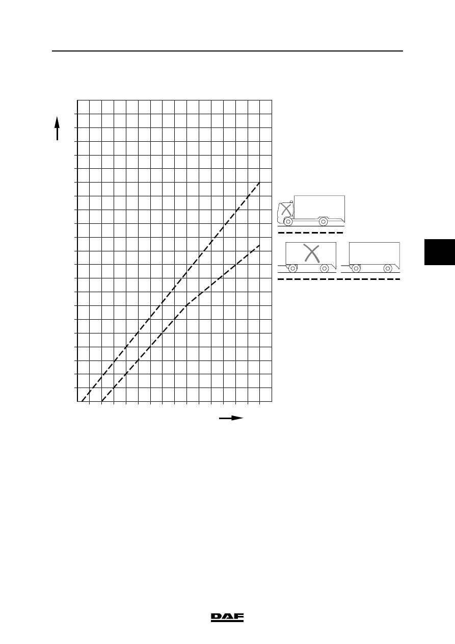
1.6 EC BAND FOR A LADEN TRUCK/TRAILER COMBINATION

The "EC band" indicates the limits within which 

the deceleration value must lie.

The "EC band" applies to:

-

truck with conventional brake system.

-

trailer with conventional or EBS brake 

system.

Note:

The following applies to mid-axle trailers fitted 

with air brakes:

The permissible ratio between the deceleration 

and the pressure at the yellow coupling head of a 

laden mid-axle trailer with air brakes should be 

within the two areas derived from the EC band for 

a laden truck/trailer combination, for which the 

vertical scale has been multiplied by 0.95.

100

%

90

80

70

60

50

40

30

20

10

0

1

0

2

3

4

5

6

7

8

R600880

P (bar)

EBS

EBS

a

EBS

BRAKING PERFORMANCE AND BRAKE EQUALISATION

1-10

©

 200436

General

5

ΛΦ45/55 series

6

©

 200436

2-1

Inspection and adjustment

BRAKING PERFORMANCE AND BRAKE EQUALISATION

ΛΦ45/55 series

6

5

2. INSPECTION AND ADJUSTMENT

2.1 INSPECTING AND ADJUSTING BRAKE EQUALISATION OF NON-EBS 

TRUCK WITH NON-EBS TRAILER VEHICLE

Inspecting brake equalisation of non-EBS 
truck with non-EBS trailer vehicle
1.

Take a test drive and evaluate the braking 

behaviour.

2.

In the case of disc brakes, inspect the 

mechanical condition of the brake calliper, 

brake disc and brake pads. In the case of 

drum brakes, inspect the mechanical 

condition of the brake drums and brake 

linings. Their condition may provide clues to 

the settings that need to be made.

3.

Perform a brake equalisation test using a 

brake dynamometer and fill in the "Brake 

equalisation form for brake dynamometer". 

See "General".

4.

Evaluate the brake equalisation of the 

combination using the "EC band graph". The 

combination is correctly balanced if the 

braking performance at 2 - 3 bar for the truck 

and the trailer vehicle are in a comparable 

position in the appropriate EC band, i.e. both 

in the upper part, both in the lower part or 

both in the middle part.

Note:

On a tractor/drawn vehicle combination the 

values for the drawn vehicle may be slightly 

lower than those for the prime mover. The 

deceleration values for the truck and the 

drawn vehicle of a truck/trailer combination 

should be the same. The reason for this lies 

in the dynamic axle load displacement, 

which on semi-trailers causes a transfer of 

weight to the tractive unit, whereas on 

trailers it does not cause a transfer of weight 

to the tractive unit.

5.

Due to the adjustment of the brake pressure 

advance on the truck and/or trailer vehicle 

the deceleration lines in the "EC band graph" 

can be affected.

Note:

For optimum interchangeability of vehicles, 

the correct choice between these two 

alternatives must be made.

BRAKING PERFORMANCE AND BRAKE EQUALISATION

2-2

©

 200436

Inspection and adjustment

5

ΛΦ45/55 series

6

6.

If the mechanical condition of the wheel 

brakes, the results of the test drive and the 

data obtained from the brake equalisation 

test using the brake dynamometer give 

cause for doing so, the brake pressure 

advance of the trailer vehicle control valve 

can be adjusted.

Adjusting brake equalisation of non-EBS 
truck with non-EBS trailer vehicle
1.

When the brake pressure advance in the 

trailer vehicle control valve on the truck is 

increased or decreased, the position of the 

curve for the trailer vehicle (B) in the graph 

will not be affected. This is because the 

reference pressures are measured at the 

yellow coupling head (= service line). For the 

same reason, however, the curve for the 

truck (A) will shift to the right or the left (will 

appear to be lower or higher respectively).

So the horizontal axis indicates how much 

the brake pressure advance has to be 

changed. Reducing the brake pressure 

advance results in increased deceleration of 

the truck. Increasing the brake pressure 

advance results in decreased deceleration of 

the truck.

Note:

Increasing the brake pressure advance on 

the trailer vehicle reaction valve on the trailer 

vehicle results in increased deceleration of 

the trailer vehicle.

Bear in mind that an increase in the 

brake pressure advance does not 

necessarily improve the braking 

performance of the trailer vehicle. It 

only means that the brake pressure 

balance between prime mover and 

trailer vehicle is changed. Moreover, 

in the event of an emergency stop 

the poorer braking performance of 

the trailer vehicle will again be 

noticeable, as the brake pressure 

advance is eliminated when the 

maximum brake pressure is used.

2.

So the horizontal axis indicates how much 

the brake pressure advance has to be 

changed.

3.

Take a test run, perform a brake equalisation 

test using a brake dynamometer and fill in 

the "Brake equalisation form for brake 

dynamometer". See "General". If desired or 

required, the setting of the trailer vehicle 

control valve can be adjusted again.

R600774

0

10

20

30

40

50

60

70

80

a

(%)

A

B

1

2

3

4

5

6

7

8

p(bar)

}


Content   ..  476  477  478  479   ..