DAF LF45, LF55 Series. Manual - part 457


  Index      DAF     DAF LF45, LF55 Series - service repair manual


Search            


Content   ..  455  456  457  458   ..


DAF LF45, LF55 Series. Manual - part 457


©

 200436

2-7

Inspection and adjustment

BRAKE SYSTEM AND COMPONENTS

ΛΦ45/55 series

6

4

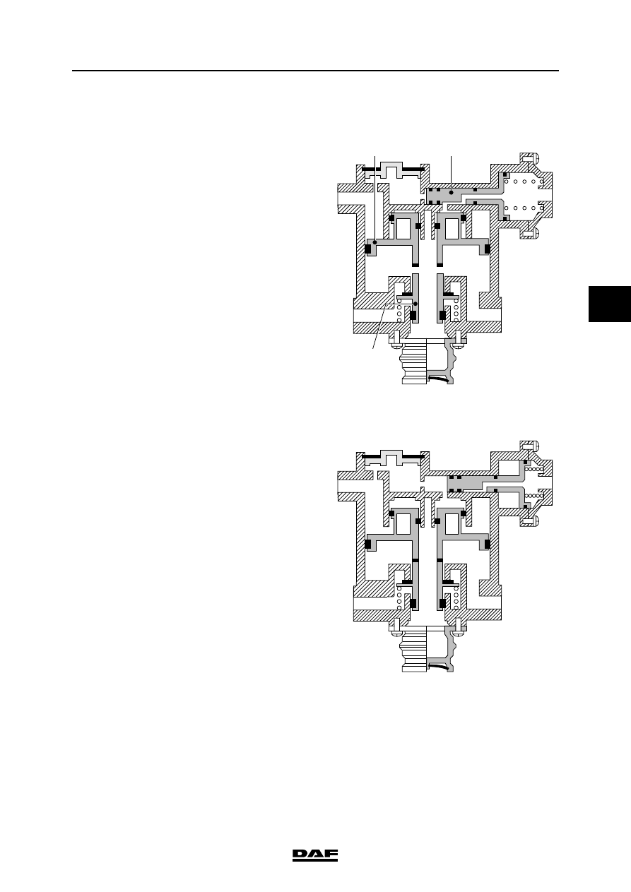
2.5 INSPECTION EMPTY/LOAD RELAY VALVE

1.

Using a T-piece, connect a pressure gauge 

to connecting point 41.

2.

Connect a pressure gauge to the test 

connection on one of the brake chambers of 

the front axle.

3.

Connect a pressure gauge to the test 

connection on one of the brake chambers of 

the rear axle.

4.

Pressurise the system.

Testing when empty
1.

Set the load sensing valve to the empty 

position.

2.

Slowly depress the brake pedal.

The pressure on the front axle should rise 

gradually, not in jumps.

The pressure on the front axle will rise less 

quickly than that on connecting point 41. 

(With an empty vehicle, the difference will be 

greater than with a partially loaded vehicle).

1

2

3

42

41

R600904

4

6

5

1

2

3

42

41

R600905

BRAKE SYSTEM AND COMPONENTS

2-8

©

 200436

Inspection and adjustment

4

ΛΦ45/55 series

6

Testing when fully loaded
1.

Set the load sensing valve to the full-load 

position.

2.

Slowly depress the brake pedal.

The pressure on the front axle should rise 

gradually, not in jumps.

The pressure on the front axle will rise as 

quickly (approx. 0.2 bar) as that on 

connection point 41. It must be possible to 

approximate the system pressure.

Inspection when faulty
1.

Disconnect the pipe to connecting point 42 

and plug off the pipe.

2.

Repeat point 8.

3.

Set the load sensing valve as specified.

4.

Reconnect the pipes to points 41 and 42 in 

the original manner.

5.

Remove the pressure gauges.

Inspection, output pressure to the front axle
1.

Measure the rear axle load.

2.

Check the load sensing valve setting.

3.

Connect a pressure gauge to the test 

connection for the load sensing valve (input 

pressure) and a pressure gauge to the test 

connection on the brake cylinder of the front 

axle.

4.

Make sure that the reservoir pressure 

exceeds 6.5 bar.

5.

Depress the brake pedal until the pressure 

gauge on the test connection of the load 

sensing valve reads 6 bar, and read off the 

braking pressure on the pressure gauge of 

the front axle.

6.

Compare this value with the data in the table 

attached to the door pillar.

0

0,1

0,25

1

1

2

2

3

3

4

4

5

5

6

6

7

7

8

8

9

9

10

10

+

_

R600906

P

0

42

=

P

42

P

41

=

0

0,1

0,5

1

1

2

2

3

3

4

4

5

5

6

6

7

7

8

8

9

9

10

10

P

0

42

=

P

42

P

41

=

1:2,7

1:1,5

41(bar)

p

2(bar)

p

R600745

©

 200436

2-9

Inspection and adjustment

BRAKE SYSTEM AND COMPONENTS

ΛΦ45/55 series

6

4

2.6 INSPECTING THE RELAY VALVE

Inspecting the relay valve
1.

Connect a pressure gauge to connecting 

point 4 of the relay valve.

2.

Connect a pressure gauge to connecting 

point 2 of the relay valve.

3.

Pressurise the system.

4.

Depending on the position of the relay valve 

in the brake system, slowly activate the 

service brake or parking brake.

5.

The pressure in the pressure gauge 

connected to connection point 4 must now 

increase to approx. 0.8 bar (the increased 

parking brake actuating pressure) or 0.5 bar 

(service brake), without there being any 

noticeable pressure on connection point 2. 

From this point, the pressures in both 

pressure gauges must increase identically. 

The pressure on the gauge connected to 

point 2 should not rise in jumps. Both gauges 

should indicate a value corresponding to the 

graph. See "Technical data".

R600490

2

1

6

4

A

5

3

7

BRAKE SYSTEM AND COMPONENTS

2-10

©

 200436

Inspection and adjustment

4

ΛΦ45/55 series

6

2.7 INSPECTION, TRAILER VEHICLE CONTROL VALVE

1.

Ensure there is sufficient system pressure.

2.

Check whether air is escaping via the bleed 

vent.

3.

Depress the brake pedal, and again check 

for leaks.

4.

Disconnect the pipe at connecting point 42 

and plug off this pipe.

5.

Depress the brake pedal, and check for 

pressure build-up in the service pipe (see 

"Technical data").

6.

Reconnect the pipe.

7.

Repeat the last three points, but now for 

connecting point 41.

8.

Operate the parking brake: pressure should 

build up in the service pipe (see "Technical 

data").

9.

Operate the parking brake to the stop, and 

lock the lever: the service pipe should once 

again become pressureless.

10. Simulate a leak in the service pipe, and 

depress the brake pedal; within two seconds, 

the outflow of air from the leak should slow 

down considerably.

R600340


Content   ..  455  456  457  458   ..