DAF LF45, LF55 Series. Manual - part 452


  Index      DAF     DAF LF45, LF55 Series - service repair manual


Search            


Content   ..  450  451  452  453   ..


DAF LF45, LF55 Series. Manual - part 452


©

 200436

2-29

Description of components

OPERATION OF BRAKE COMPONENTS

ΛΦ45/55 series

6

3

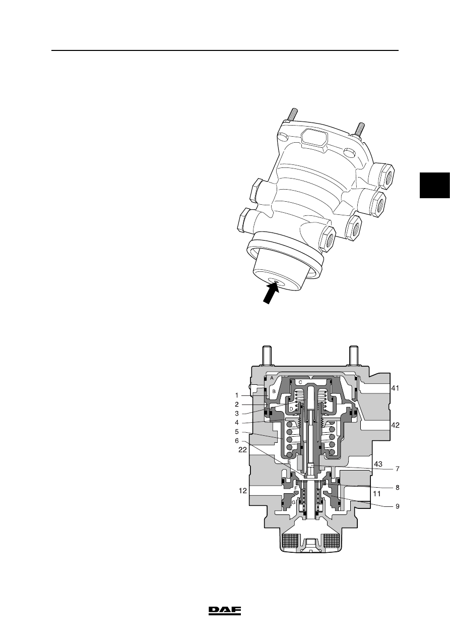
2.16 TRAILER CONTROL VALVE

Purpose
The purpose of the trailer vehicle control valve is 

to pass on the brake commands from the prime 

mover to the trailer vehicle.

Operation

Driving
Connecting point 11 is connected to a reservoir 

and connecting point 43 to the parking brake 

valve. Both are pressurised and in a state of 

equilibrium. The service coupling head 

communicates with the ambient air via 

connecting point 22, valve 8 and the bleed vent 

with damper.

41

42

43

11

12

22

R600335

R600340

OPERATION OF BRAKE COMPONENTS

2-30

©

 200436

Description of components

3

ΛΦ45/55 series

6

Braking with the service brake

Pressure build-up
Using the foot brake valve, circuit 1, connecting 

point 41, and circuit 2, connecting point 42, are 

pressurised.

This pushes down the pistons (1 and 2), causing 

valve 8 to close the outlet and open the inlet. The 

brake pressure at connecting point 11 can now 

flow via valve 8 to connecting point 22, (yellow) 

trailer vehicle service coupling head, and will 

cause the trailer vehicle to brake.

Adjusting
When a pre-set output pressure has been 

reached at connecting point 22, this pressure will 

once again force the piston (5) upwards, thus 

closing valve 8.

There is now a state of balance between the input 

pressure at connecting point 41 and the output 

pressure at connecting point 22.

Releasing
When the foot brake valve is released, the input 

pressure at connecting points 41 and 42 falls 

away. Pistons 1 and 2 are pushed upwards by the 

spring under the spring retainer (4).

As a result, valve 8 is closed and the outlet 

opened, linking connecting point 22 with the 

bleed vent.

R600340

©

 200436

2-31

Description of components

OPERATION OF BRAKE COMPONENTS

ΛΦ45/55 series

6

3

Advance

Pressure build-up
If the foot brake valve is used to build up pressure 

at connecting points 41 and 42, the output 

pressure at connecting point 22 will also move 

piston 5 upwards, closing valve 8.

There is now a state of balance between the input 

pressure at connecting point 41 and the output 

pressure at connecting point 22.

Alteration
If adjusting screw 6 is turned clockwise, for 

example, the spring retainer (4) will be moved 

downwards, compressing the spring underneath 

it. Therefore, if the operating pressure at 

connecting points 41 and 42 remains the same, a 

higher adjusting pressure will be needed under 

piston 5. This adjusting pressure is also on the 

yellow coupling head.

This increase of service pressure to the trailer 

vehicle in relation to the braking pressure from 

the prime mover is called advance.

For the setting procedure, see "Inspection and 

adjustment".

Emergency brake
When the parking brake valve is moved into the 

locking position, connecting point 43 will be 

gradually bled.

Piston 9 moves upwards and valve 8 is opened.

Depending on the drop in pressure at connection 

point 43, a pressure build-up will occur at 

connection point 22. When a pre-set value has 

been reached, valve 8 will close, so that a state of 

equilibrium is achieved.

Parking brake
When the parking brake valve is in its maximum 

position, causing the lever to be locked, 

connecting point 43 is bled. As a consequence, 

there is still output pressure at connecting 

point 22.

Protection against breakage of service line
During braking, pressure will build up at 

connecting point 22. The air necessary for this is 

supplied from connecting point 11.

If the service line is broken, pressure will not build 

up in space E, which will cause piston 9 to move 

up and close against the bottom of valve 8. The 

supply from connecting point 11 stagnates, 

causing pressure to be delivered from connecting 

point 12.

The pressure in the reservoir pipe drops and the 

trailer brakes are applied.

R600340

OPERATION OF BRAKE COMPONENTS

2-32

©

 200436

Description of components

3

ΛΦ45/55 series

6

2.17 COUPLING HEAD

Application
With spring-loaded valve. Fitted in the dual-line 

brake system of versions with trailer vehicle 

connection.

If these automatic coupling heads are applied, 

there is no need for an air cock.

Purpose
To connect the air brake system of the prime 

mover with that of the trailer vehicle.

Operation
The spring-loaded valve (2) in the coupling head 

ensures that the system is isolated from the 

ambient air.

When coupling, turn the counter head until the 

claws of the two heads rest against the stop 

under the locking plates. This will prevent the 

coupling head from disengaging spontaneously.

Because the two sealing rings (1) are pressed 

against each other, the spring-loaded valve 

remains open so that an air-tight connection is 

achieved. When the heads are uncoupled, the 

spring-loaded valve will seal off the pipe on the 

prime mover.

The coupling head is equipped with a safety cam. 

This is to prevent different coupling heads being 

coupled to one another.

If no trailer vehicle is hooked up, the cover of the 

coupling head must be closed, to avoid fouling.

R600899

R600900

2

1

R600901

2

1


Content   ..  450  451  452  453   ..