DAF LF45, LF55 Series. Manual - part 447
©
200436
2-9
Description of components
OPERATION OF BRAKE COMPONENTS
ΛΦ45/55 series
6
3
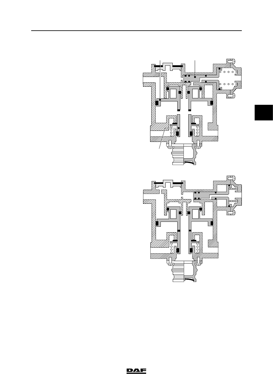
Empty/load relay valve
In rest position, relay piston 4 is in its upper
position and connecting point 2 (brake cylinders
on front axle) is bled via connecting point 3.
When the foot brake is applied, the relay piston is
forced downwards via connecting point 41, thus
opening valve 5. At connecting point 2 pressure is
built up until a set value is reached. Relay piston
4 is then once again forced upwards until there is
a state of equilibrium.
Air has also entered simultaneously via
connection point 42 (load sensing valve). This will
force piston 6 to the left. Through a bore in piston
6 the pressure now also reaches the central
surface of the relay piston (4). This pressure will
depend on the loading of the rear axle. As a
consequence, the output pressure of this valve is
in part dependent on the braking pressure of the
rear axle.
The input pressure at connecting point 41 is also
applied to the left-hand side of piston 6, via two
openings. If no pressure enters via connecting
point 42, due to a fault, piston 6 will be forced to
the right. The pressure at connecting point 41 will
now also reach the central surface of relay piston
4. In this situation, the valve simply operates as a
relay valve, and will no longer reduce.
When the foot brake is released, the pressure at
connecting points 41 and 42 will disappear. Relay
piston 4 will be forced upwards by the pressure
beneath it, thus opening the bleed system.
1
2
3
42
41
R600493
4
6
5
1
2
3
42
41
R600494