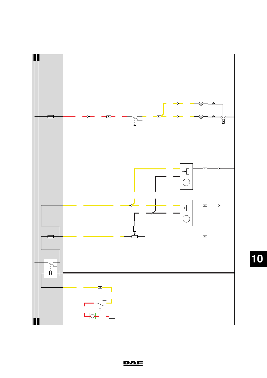
DAF LF45, LF55 Series. Manual - part 404
29
1427090/03
EL001600
1
2
3
4
5
6
7
8
9
10
11
12
13
14
15
16
17
18
19
20
21
22
23
24
25
26
27
28
29
30
31
32
33
34
35
36
37
38
39
40
41
42
43
44
45
46
47
48
49
50
51
52
53
1000
2100
2100
2169
2169
2169
2169
1000
4953
4953
2169
4953
2169
2169
4953
2169
1104
1104
1104
2018
2018
2018
2018
2018
E349
1
2
2
4
1
C622
A13/702
A11/702
1/707
B4/703
4
722
3
722
2
815
2
814
1
815
1
814
C871
2
4
1
31
B129
M
2
31
B130
M
2
1
722
2
722
B7/701
D942
1010
1000
1010
1000
2101
2169
2100
E283
E163
10A
G000
3
1
24
5
M
20A
5
71
0I
C715
1
736
C145
1
2
C144
1
2
200440
2-105
5
ELECTRICAL SYSTEM
Electrical system
series
45/55
LF