DAF LF45, LF55 Series. Manual - part 395
17
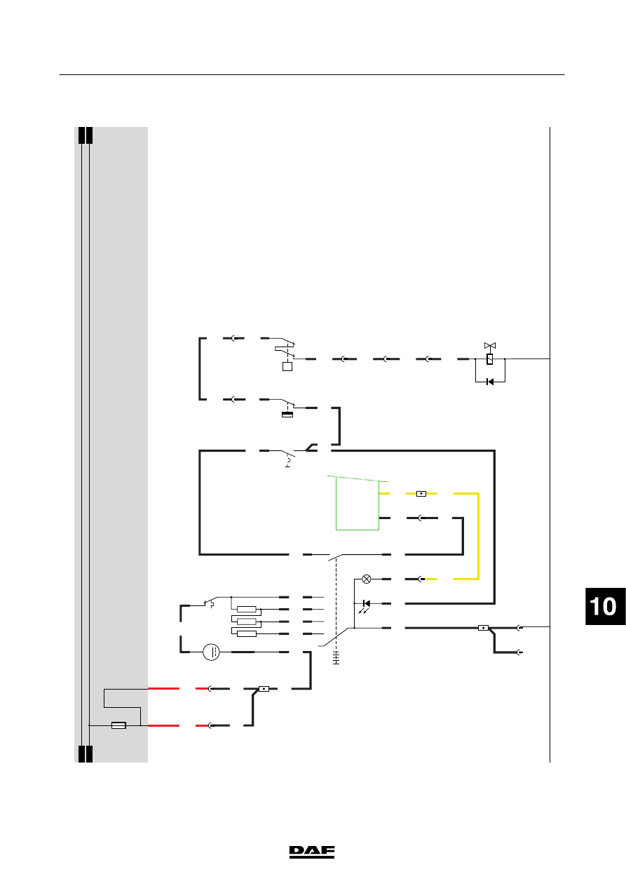
1427090/03
EL001579
1
2
3
4
5
6
7
8
9
10
11
12
13
14
15
16
17
18
19
20
21
22
23
24
25
26
27
28
29
30
31
32
33
34
35
36
37
38
39
40
41
42
43
44
45
46
47
48
49
50
51
52
53
5189
4655
4655
2622
5055
5055
5055
1201
1201
RD
RD
RD
RD
GS
OE
RD
RD
ZT
ZT
BW
GL
GN
VT
GL
GS
GS
GS
GL
RD
5055
2622
2622
3
768
3
720
2
734
A11/701
8
751
B10/701
7
751
5
751
2
751
1
751
D942
1010
1000
1010
1000
E031
15A
1201
2
1
B043
6
751
4
751
4655
1
734
D900
A1/
743
C49/
745
E509
1
2
P
D787
1
2
E508
3
1
B377
M
1243
5
+
7
02
01
C893
2
1
B5
A5
B3
B4
A2
C892
A4
A1
B1
B2
200440
2-69
5
ELECTRICAL SYSTEM
Electrical system
series
45/55
LF