DAF LF45, LF55 Series. Manual - part 381


  Index      DAF     DAF LF45, LF55 Series - service repair manual


Search            


Content   ..  379  380  381  382   ..


DAF LF45, LF55 Series. Manual - part 381


5

LF45/55 series

Electrical system

ELECTRICAL SYSTEM

2-13

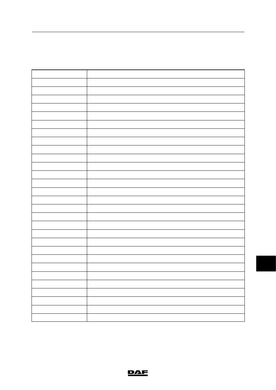
2.3 SECTION DIAGRAMS FROM CIRCUIT DIAGRAM 1427090/03

Overview of section diagrams of circuit

diagram 1427090/03

Section diagram no.

Title of section diagram

A

Voltage before and after contact

B

Overview of earthing points

C

CAN overview

1

Main switch

2

Ignition/starter switch/charging circuit

3

MTCO tachograph

4

Immobiliser

5

Pre-glowing

6

DIP-4

7

Direction indicators/warning lamps

8

VIC

9

Marker lights/parking lights/tail lights

10

Reversing lights/buzzer

11

Lighting/dipped beam/main beam/Swedish lighting/fog lamps

12

Stop lights/cab tilting gear

13

Differential lock

14

Interior lighting

15

Mirror heating/windscreen heating/mirror adjustment

16

Search lighting

17

Air conditioning/heater fan

18

Seat heating/accessories connection

19

Horn/cigar lighter/work lamp/air dryer

20

ABS-D

21

ABS/ASR-E

22

ECS-DC3/exhaust brake

23

Cruise control

24

AGC automatic transmission (AT1000/2000)

25

AGC automatic transmission (MD3060)

26

PTO

10

 200440

5

ELECTRICAL SYSTEM

Electrical system

LF45/55 series

2-14

Section diagram no.

Title of section diagram

27A

ECAS-3 LF45

27B

ECAS-3 LF55

27C

ECAS-2 LF55

29

Headlamp height adjustment/rotating beams

30

24/12 V 10/15 A converter for radio

31

CDS-3/drop glass operation/roof hatch

33

Windscreen wipe/wash system

34

ACH-W with timer

35

Application connectors, engine speed control, superstructure functions

and spare wiring

36

Break lining wear

37

ALS-S/battery charger, alarm BV2/BV3

38

Sockets, FA/FT

39

Water separator/fuel pre-heating

40

Airbag/seat belt tensioner

41

RAS-EC

10

 200440

5

LF45/55 series

Electrical system

ELECTRICAL SYSTEM

2-15

10

 200440

A

V

OL

TA

GE

BEFORE

AND

AFTER

C

ONT

ACT

VOL

TA

GE

BEFORE

CONT

ACT

Wire

1000

runs

from

the

batteries

(A500)

to

the

starter

motor

(B010),

connecting

point

30,

and

via

the

main

fuse

(E349,

80

A)

to

dashboard

lead-through

zone

1.

Wire

1000

runs

from

the

glow

plug

relay

fuse

(E286,

125

A)

to

the

glow

plug

relay

(G014).

W

ire

1000

and

the

+

distribution

bolt

in

dashboard

lead-through

zone

1

provide

a

constant

voltage

at

pins

1

and

2

of

connector

705

on

the

P

CB.

This

provides

“voltage

before

contact”

for

the

entire

P

CB.

P

ower

is

also

provided

(by

w

ire

1000)

from

point

30

on

the

starter

motor

to

the

B+1

connection

of

the

alternator

(A513).

W

ire

1000

goes

from

the

+

distribution

bolt

to

the

ignition/starter

switch

(C841).

VOL

TA

GE

AFTER

C

ONT

ACT

When

the

ignition/starter

switch

(C841)

is

set

to

the

“contact”

position

(connection

between

points

1

and

4),

relay

G015

is

energised

via

wire

4001.

This

then

connects

wire

1000

(voltage

before

contact)

to

wire

1010

(voltage

after

contact).

When

the

ignition/starter

switch

(C841)

is

turned

against

the

spring

pressure

(connection

between

points

1

and

2),

relay

G015

remains

activated.

When

the

ignition/starter

key

is

released,

the

contact/starter

switch

automatically

springs

back

and

remains

in

the

“contact”

position.

200440

2-16

5

ELECTRICAL SYSTEM

Electrical system

series

45/55

LF


Content   ..  379  380  381  382   ..