DAF LF45, LF55 Series. Manual - part 367
5
LF45/55 series
Location of connectors
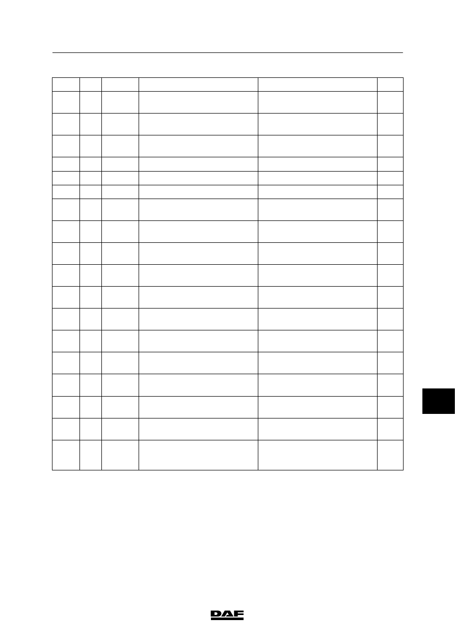
LOCATION OF CONNECTORS
1-7
1
2
3
4
5
6
836
4
Black
Oil level sensor, RAS-EC
Next to oil tank, on left under
cab
27
837
68
Black
Connector, RAS-EC electronic
unit
In between two cross members
halfway between two rear axles
27
838
4
Black
Angle sensor, rear, RAS-EC
On left-hand brake booster,
trailing axle
27
839
4
Black
Front axle angle sensor 1
On top of steering box
27
840
3
Black
Front axle angle sensor 2
On bottom of steering box
27
841
7
Black
Steering valve, RAS-EC
On rear axle cross member
27
842
2
Black
Wheel speed sensor, RAS-EC
On inside of left-hand chassis
side member, near rear axles
27
843
13
Black
Automatic gearbox selector
(MD3060)
Left-hand chassis side member,
near fuel tank
28
844
2
Black
Activation of cooling fans,
automatic gearbox
On chassis in AGC box
28
845
1
Black
Temperature switch, cooling
fans, automatic gearbox
On chassis in AGC box
28
846
2
Black
Temperature switch, cooling
fans, automatic gearbox
On oil cooler radiator unit
29
847
2
Black
Activation of cooling fan 1,
automatic gearbox
On oil cooler radiator unit
29
848
2
Black
Activation of cooling fan 2,
automatic gearbox
On oil cooler radiator unit
29
849
1
White
Light, automatic gearbox
selector (MD3060)
Underside of central box
29
850
6
Black
Intermediate connector for
diagnostic connector
Inside of left-hand chassis side
member
28
851
4
Black
Activates PTO valve
Inside of right-hand chassis
side member
26
852
4
Black
“Remote throttle” application
Chassis cross member behind
gearbox
25
853
32
Grey
Connector, electronic unit,
automatic gearbox
(AT1000/2000)
On chassis in AGC box
31
9
200440