DAF LF45, LF55 Series. Manual - part 331


  Index      DAF     DAF LF45, LF55 Series - service repair manual


Search            


Content   ..  329  330  331  332   ..


DAF LF45, LF55 Series. Manual - part 331


©

 200416

2-1

General

ENGINE BRAKE, CE ENGINE

ΛΦ45/55 series

4

7

2. GENERAL

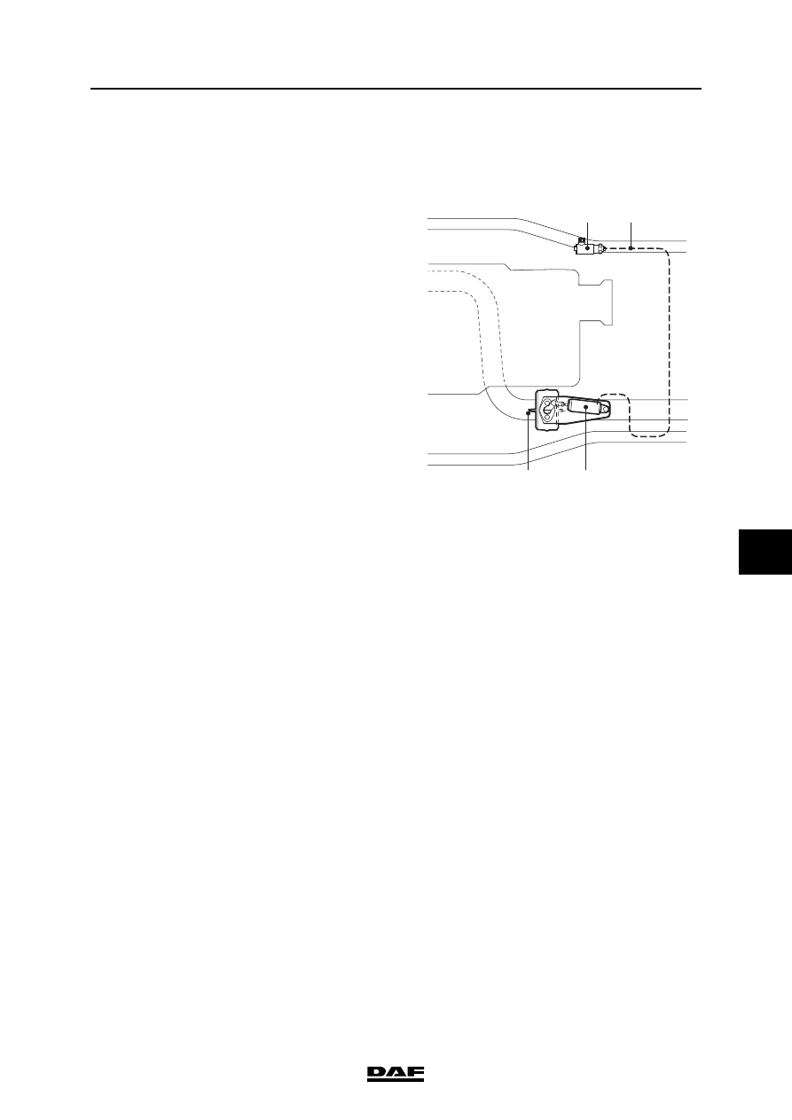
2.1 LOCATION OF EXHAUST BRAKE COMPONENTS

1.

Exhaust brake valve

2.

Air pipe

3.

Operating cylinder, exhaust brake

4.

Butterfly valve

1

3

4

2

i400858

ENGINE BRAKE, CE ENGINE

2-2

©

 200416

General

7

ΛΦ45/55 series

4

2.2 SYSTEM DESCRIPTION, EXHAUST BRAKE

Note:

The engine brake is an exhaust brake.

Switching on the exhaust brake
The exhaust brake consists of an engine brake 

operating switch fitted to the steering column and 

an operating cylinder (3) connected to the 

butterfly valve (4) in the exhaust pipe.

If the exhaust brake operating switch is activated, 

a signal is passed to the engine management 

system's electronic unit. The operating switch 

has the positions "off" and "automatic". In the 

"automatic" position the engine management 

system's electronic unit engages the exhaust 

brake whenever this is appropriate and possible. 

Of course, the electronic unit disengages the 

exhaust brake when required. 

If the exhaust brake is engaged by the electronic 

unit, the unit energises the exhaust brake valve 

(1), causing supply pressure to flow to the 

operating cylinder. The cylinder closes the 

butterfly valve in the butterfly valve housing. The 

exhaust pipe is then almost completely closed off. 

The engine management system's electronic unit 

also interrupts the fuel supply to the various 

cylinders. The engine now acts as a compressor, 

creating a braking action.

The higher the engine speed, the greater the 

braking action of the engine brake.

Switching off the exhaust brake
If the engine brake control switch is pushed back, 

the butterfly valve will be re-opened and the fuel 

supply to the various cylinders will be re-instated.

1

3

4

2

i400858

1.

Exhaust brake valve

2.

Air pipe

3.

Butterfly valve operating cylinder

4.

Butterfly valve

©

 200416

3-1

Inspection and adjustment

ENGINE BRAKE, CE ENGINE

ΛΦ45/55 series

4

7

3. INSPECTION AND ADJUSTMENT

3.1 INSPECTION AND ADJUSTMENT, EXHAUST BRAKE

Checking exhaust brake
1.

Check the exhaust brake for smooth 

operation by pressurising the exhaust brake 

cylinder yourself.

Setting the exhaust brake
1.

Remove the air pipe from the operating 

cylinder.

2.

Slacken lock nut (1) on the piston rod.

3.

Remove the attachment nut (2) from the 

operating cylinder and take the operating 

cylinder off the support.

4.

Open the butterfly valve fully (exhaust brake 

inactive), indicated by the mark (3) on the 

butterfly valve shaft, and press the lever (4) 

against the stop.

5.

Set the piston rod length by rotating the 

operating cylinder in such a way that it can 

be fitted on the support.

6.

Turn the piston rod one more full turn in the 

ball joint to give the operating cylinder the 

correct pre-tension.

7.

Fit the operating cylinder on the support 

using the attachment nut (2) and fit the air 

pipe.

8.

Tighten the lock nut (1).

9.

Connect the air pipe to the operating 

cylinder.

i400859

1

4

3

2

ENGINE BRAKE, CE ENGINE

3-2

©

 200416

Inspection and adjustment

7

ΛΦ45/55 series

4


Content   ..  329  330  331  332   ..