DAF LF45, LF55 Series. Manual - part 326


  Index      DAF     DAF LF45, LF55 Series - service repair manual


Search            


Content   ..  324  325  326  327   ..


DAF LF45, LF55 Series. Manual - part 326


©

 200416

3-1

Inspection and adjustment

CE ENGINE INLET/EXHAUST SYSTEM

ΛΦ45/55 series

4

6

3. INSPECTION AND ADJUSTMENT

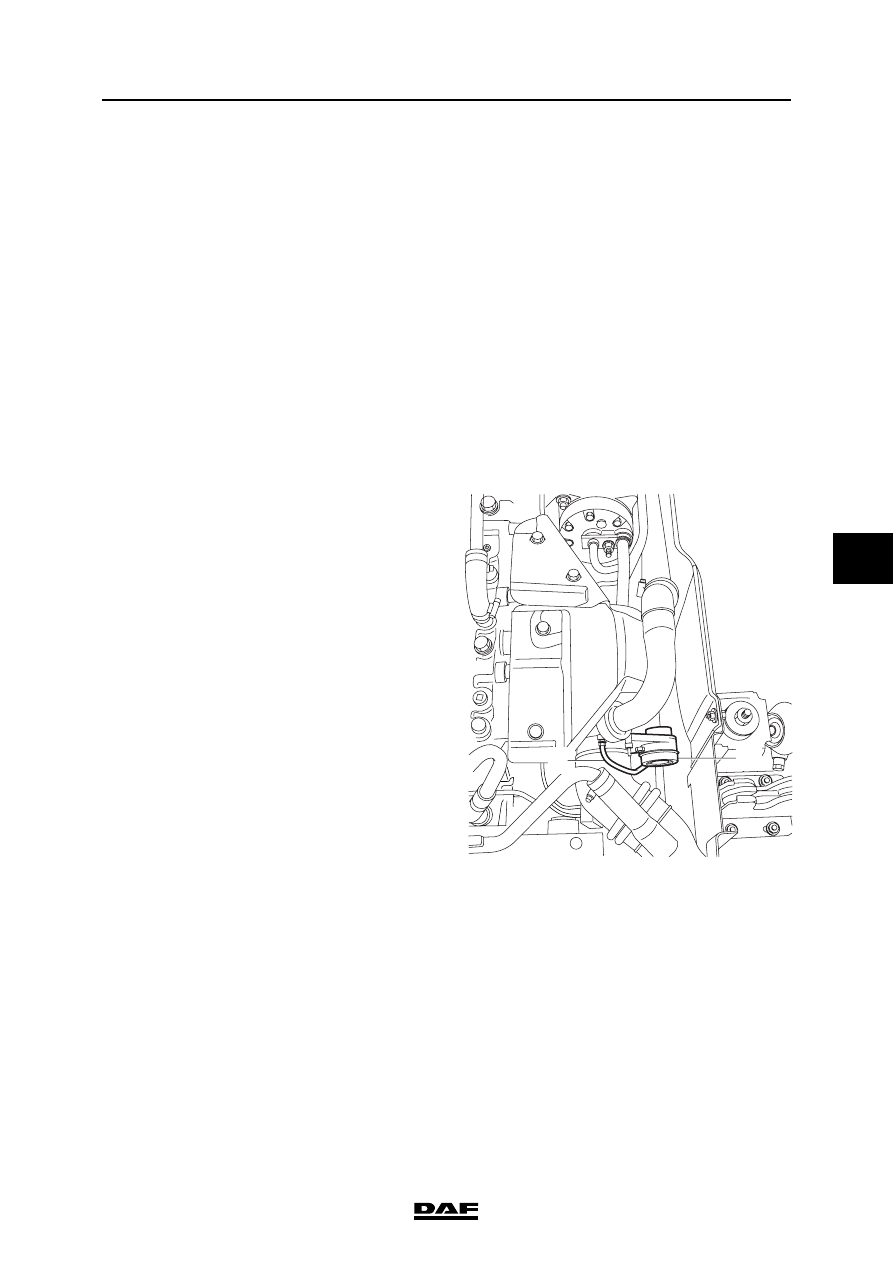
3.1 INSPECTING TURBOCHARGER WASTEGATE

Note:

Depending on the fitting position of the 

turbocharger, it may be necessary to remove the 

turbocharger from the engine before this 

adjustment; see "Removal and installation".

Note:

The turbocharger is calibrated in the factory and 

must not be re-adjusted. The length of the control 

rod on the wastegate valve lever may only be 

changed when assembling a new turbocharger. 

After that, only an inspection of the actuating 

pressure of the wastegate may be carried out. If 

the result is negative, the turbocharger must be 

replaced.

1.

Remove the flexible pipe (2) from the 

diaphragm box (1) of the wastegate.

2.

Connect an air-pressure reducer valve to the 

diaphragm box of the wastegate. Set the 

reducer valve to max. 0.2 bar gauge 

pressure. Connect the reducer valve to a 

compressed air installation.

3.

Set the reducer valve to exactly the same 

test pressure as listed in "Technical data".

4.

Check the diaphragm in the diaphragm box 

for leaks by listening carefully for a hissing 

sound from the diaphragm box.

5.

Check whether the control rod of the 

wastegate has moved. If it has not moved, 

the control rod must be loosened from the 

lever. Check again whether the control rod 

has moved. If is has not moved, the 

diaphragm box must be replaced. If it has 

moved, the wastegate valve must be made 

to move freely or, if that does not help 

sufficiently, the entire compressor unit must 

be replaced.

6.

Remove the flexible pipe with the reducer 

valve and re-connect the flexible pipe of the 

compressor pump to the wastegate 

diaphragm box.

2

1

i400510

CE ENGINE INLET/EXHAUST SYSTEM

3-2

©

 200416

Inspection and adjustment

6

ΛΦ45/55 series

4

3.2 INSPECTING TURBOCHARGER AXIAL BEARING PLAY

Note:

The turbocharger axial bearing play should only 

be checked when the engine is cold.

1.

Remove the exhaust pipe from the 

turbocharger.

2.

Remove the charge pipes from the 

turbocharger.

3.

Fit a dial gauge (1) to the charge supply 

flange of the turbocharger.

4.

Push the compressor shaft away from the 

dial gauge and set the gauge to zero.

5.

Push the compressor shaft to the dial gauge 

and read off the axial play. Compare the 

reading with the specified value; see 

"Technical data". Replace the turbocharger if 

necessary.

6.

Fit the charge pipes to the turbocharger.

7.

Fit the exhaust pipe to the turbocharger.

i400821

1

©

 200416

3-3

Inspection and adjustment

CE ENGINE INLET/EXHAUST SYSTEM

ΛΦ45/55 series

4

6

3.3 INSPECTING TURBOCHARGER RADIAL BEARING PLAY

Note:

The turbocharger radial bearing play should only 

be checked when the engine is cold.

1.

Remove the turbocharger from the exhaust 

manifold. See "Removal and installation".

2.

Fit a pressure gauge to the turbocharger 

housing and measure the radial play. 

Compare the reading with the specified 

value; see "Technical data". Replace the 

turbocharger if necessary.

3.

Fit the turbocharger. See "Removal and 

installation".

i400650

CE ENGINE INLET/EXHAUST SYSTEM

3-4

©

 200416

Inspection and adjustment

6

ΛΦ45/55 series

4

3.4 CHECKING EXHAUST GAS BACK PRESSURE

Checking exhaust gas back pressure
1.

Remove the plug from the exhaust elbow 

attachment or bore a hole and install a 

suitable coupling with a pipe. The first part of 

the pipe must be made of metal, to withstand 

the high temperatures.

Note:

Use an attenuated gauge to prevent 

excessive shaking of the gauge needle.

2.

Connect a pressure gauge to the pipe, with a 

range of at least 0.1 - 0.2 bar (10 - 20 kPa).

Note:

The engine brake must not be used during 

measurements. This is to protect the 

pressure gauge.

3.

Measure the exhaust gas back pressure at 

full-load engine speed and compare the 

measurements to the specified value. See 

"Technical data". Check the exhaust system 

if the exhaust gas back pressure is too high.

4.

Remove the pressure gauge and the 

coupling and fit the plug.

i400513


Content   ..  324  325  326  327   ..