DAF LF45, LF55 Series. Manual - part 270


  Index      DAF     DAF LF45, LF55 Series - service repair manual


Search            


Content   ..  268  269  270  271   ..


DAF LF45, LF55 Series. Manual - part 270


©

 200508

5-3

Removal and installation

CLUTCH

ΛΦ45/55 series

3

9

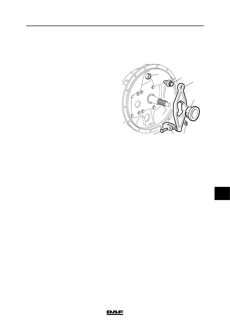
5.3 REMOVAL AND INSTALLATION, CLUTCH LEVER

Removing clutch lever
1.

Remove the gearbox.

2.

Remove the thrust bearing (4).

3.

Remove the clip (5) and the yoke pin (7).

4.

Force the ball joint (2) which is installed in the 

clutch lever (3) out of the attachment point in 

the clutch housing.

Note:

It may be possible to remove the complete 

support point (1) by turning the attachment 

point out of the clutch housing. 

Fitting clutch lever
1.

Apply a little grease to the moving parts of 

the clutch lever.

2.

Lock the support point (1) in the clutch 

housing with a suitable locking compound.

3.

Install the ball joint (2) in the clutch lever (3) 

and install the clutch lever in the clutch 

housing.

4.

Install the yoke pin (7) in the claw (6) and put 

on the clip (5).

5.

Install the thrust bearing (4).

6.

Fit the gearbox.

V300397

1

2

3

4

6

7

5

CLUTCH

5-4

©

 200508

Removal and installation

9

ΛΦ45/55 series

3

5.4 REMOVAL AND INSTALLATION, CLUTCH RELEASE ASSEMBLY / CLUTCH 

PLATE

Removing clutch release assembly/clutch 
plate
1.

Remove the gearbox.

2.

Insert a dummy input shaft through the hub 

of the clutch plate in the flywheel pilot 

bearing.

3.

Remove four attachment bolts from around 

the circumference of the clutch release 

assembly. Replace them with studs.

4.

Remove the remaining attachment bolts of 

the clutch release assembly evenly.

5.

Remove the clutch release assembly by 

sliding it off the four studs.

6.

Remove the clutch plate with the dummy 

input shaft.

Installing clutch release assembly/clutch 
plate
1.

Check the free movement of the clutch plate 

on the splines of the gearbox input shaft.

2.

Lightly lubricate the end of the dummy input 

shaft with grease. This will lubricate the hub 

of the clutch plate.

3.

Use a dummy input shaft to position the 

clutch plate against the flywheel.

4.

Install four studs in the flywheel, distributed 

evenly around the circumference.

5.

Support the clutch release assembly and 

slide it onto the four studs.

6.

Fit the attachment bolts and tighten them 

crosswise to the specified torque. See 

"Technical data".

7.

Fit the gearbox.

V300124

©

 200508

5-5

Removal and installation

CLUTCH

ΛΦ45/55 series

3

9

5.5 REMOVAL AND INSTALLATION, PILOT BEARING

Removing pilot bearing
1.

Remove the gearbox.

2.

Remove the clutch release assembly and the 

clutch plate.

3.

Use an internal puller (2) to remove the pilot 

bearing (1) from the flywheel.

Fitting pilot bearing
1.

Check the flywheel bore for dirt and damage.

Note:

The pilot bearing (1) has a grease and dust seal 

(2) on one side only. When the pilot bearing is 

installed, the grease and dust seal must be on the 

clutch plate side. 

W 3 04 016

1

2

W 3 04 019

1

2

CLUTCH

5-6

©

 200508

Removal and installation

9

ΛΦ45/55 series

3

2.

Use a plastic mallet to install the bearing in 

the flywheel.

3.

Fit the clutch release assembly and clutch 

plate.

4.

Fit the gearbox.

W 3 04 017

V300989


Content   ..  268  269  270  271   ..