DAF LF45, LF55 Series. Manual - part 230
©
200508
2-1
Inspection and adjustment
MECHANICAL GEARBOX CONTROL
ΛΦ45/55 series
3
2
2. INSPECTION AND ADJUSTMENT
2.1 INSPECTING AND ADJUSTING OPERATING MECHANISM,
2 ADJUSTMENT OPTIONS
Inspecting operating mechanism,
2 adjustment options
1.
Push the control against the spring pressure
to check whether it can move freely in
neutral.
2.
Check that all gears can be engaged without
parts coming into contact with each other.
3.
During a test drive, check that the gear
remains engaged under changing
conditions.
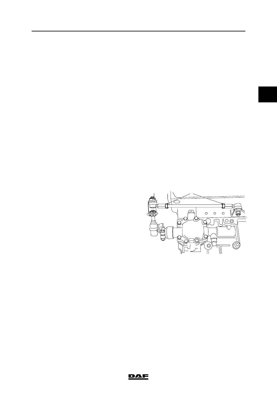
Adjusting the gearbox control,
2 adjustment options
1.
Remove the switch button (see "Removal
and installation").
2.
Remove the gaiter (see "Removal and
installation").
3.
Loosen the lock nuts (3) of the gearbox lever.
4.
Loosen the lock nuts (2) of the torque rod on
both sides.
5.
Remove attachment nut (1) from the torque
rod on control rod side.
2
1
3
V3 00 575