DAF LF45, LF55 Series. Manual - part 226
©
200508
4-5
Automatic gearbox
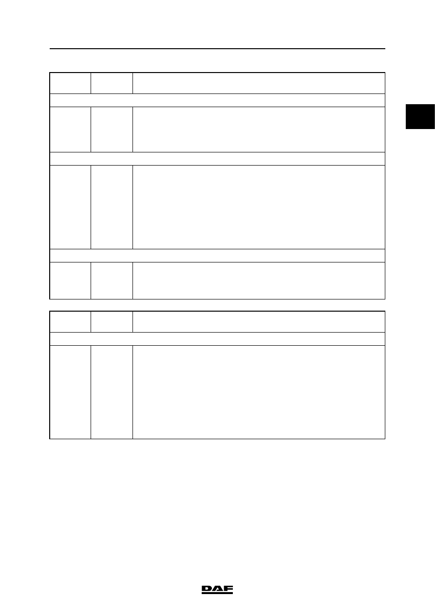
DIAGNOSTICS
ΛΦ45/55 series
3
1
EEPROM fault
34
12
13
14
15
16
1.
Re-calibrate if necessary.
2.
If re-calibration is impossible, replace the ECU.
3.
If ECU replacement is impossible, contact your Allison dealer.
EEPROM writing error as a result of loss of power supply
35
00
16
Check the following points:
1.
ECU is firmly attached, clean and undamaged.
2.
VIM (Vehicle Interface Module) is firmly attached, clean and undamaged.
3.
the vehicle manufacturer has used the specified wiring for power supply
and earth connection.
4.
battery positive pole.
5.
battery earth connection.
6.
specified connections for vehicle ignition.
If all these points are in order, contact your Allison dealer.
Hardware/software not compatible
36
00
1.
Replace ECU if possible.
2.
Re-program ECU if possible.
3.
If replacement or re-programming is not possible, contact your Allison
dealer.
Main code Sub-code
RECOMMENDED PROCEDURES
Interruption or short circuit in electromagnetic valve circuit
41
12
13
14
15
16
20
22
23
24
25
26
Check the following points:
1.
gearbox main connector is connected, is firmly attached, is clean and
undamaged.
2.
ECU connector is connected, is firmly attached, is clean and undamaged.
3.
visual inspection of the wiring harness: no damage, chafed or too taut
wires, no screws through the wiring harness.
4.
no interruptions or short circuits between wires or earth in wiring harness.
Replace wiring harness if necessary.
If all these points are in order, contact your Allison dealer.
Main code Sub-code
RECOMMENDED PROCEDURES