DAF LF45, LF55 Series. Manual - part 194


  Index      DAF     DAF LF45, LF55 Series - service repair manual


Search            


Content   ..  192  193  194  195   ..


DAF LF45, LF55 Series. Manual - part 194


©

 200505

4-7

Removing and installing

CE ENGINE

ΛΦ45/55 series

2

5

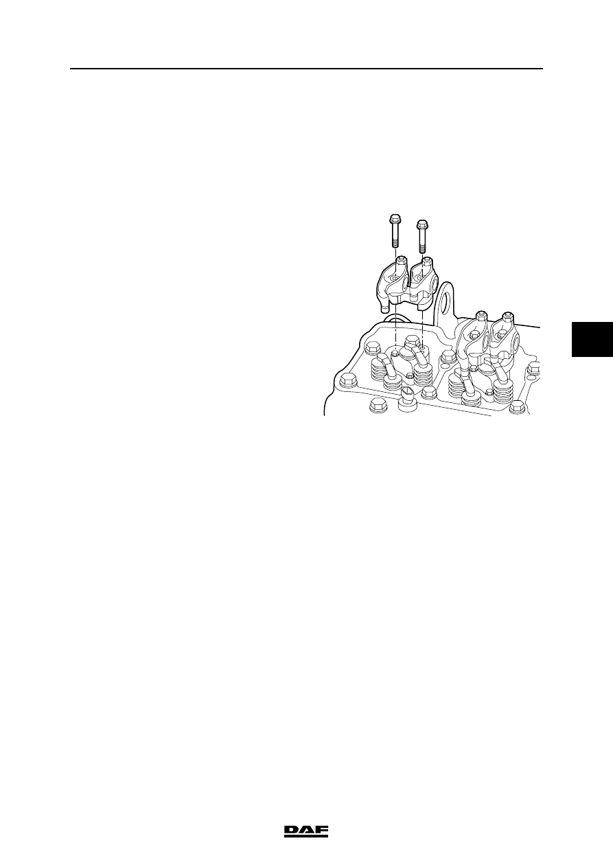
4.5 REMOVAL AND INSTALLATION, VALVE GEAR

Removing the valve gear
1.

Remove the valve cover.

2.

Loosen the lock nuts on the valve stem bolts 

and unscrew the bolts until they abut.

3.

Remove the rocker seat attachment bolts.

Note:

Number the rocker seats so that they can be 

refitted in their original position.

4.

Remove the rocker seats with the rockers.

5.

Remove the bridges.

Installing the valve gear
1.

Check that the push rods are in the correct 

position in the valve tappets and apply a drop 

of engine oil to the push rod cavity.

2.

Fit the bridges on the valves.

3.

Fit the push rods in their original position.

4.

Hand-tighten the rocker seats and rockers in 

their original position.

5.

Tighten the attachment bolts to the specified 

torque. See "Technical data".

6.

Adjust the valve clearance. See "Inspection 

and adjustment".

7.

Fit the valve cover.

M201081

CE ENGINE

4-8

©

 200505

Removing and installing

5

ΛΦ45/55 series

2

4.6 REMOVAL AND INSTALLATION, INTAKE MANIFOLD

Removing the intake manifold
1.

Remove the hose from the intake manifold 

coming from the intercooler.

2.

Detach the electric wiring from the glow 

elements (1) (if fitted) using the connectors.

3.

Remove the fuel rail.

4.

Remove the inlet air boost pressure sensor/

temperature sensor (1) from the intake 

manifold.

5.

Remove the intake manifold (2).

6.

Cover the open inlet duct from the cylinder 

head to prevent the ingress of foreign matter.

1

i400521

M201395

1

2

©

 200505

4-9

Removing and installing

CE ENGINE

ΛΦ45/55 series

2

5

Installing the intake manifold
1.

Thoroughly clean the sealing surfaces of the 

intake manifold and the cylinder head. Do 

not let any particles fall into the open inlet 

duct in the cylinder head.

2.

Apply a bead (2) of sealant to the sealing 

surfaces from the cylinder head to the intake 

manifold (1). See "Technical data".

3.

Fit the intake manifold immediately and 

tighten the attachment bolts to the specified 

torque. See "Technical data".

4.

Fit the inlet air boost pressure sensor/

temperature sensor on the intake manifold.

5.

Fit the fuel rail.

6.

Connect the electric wiring to the glow 

elements (if fitted) using the connectors (1).

7.

Fit the hose to the intake manifold coming 

from the intercooler.

M201396

1

2

1

i400521

CE ENGINE

4-10

©

 200505

Removing and installing

5

ΛΦ45/55 series

2

4.7 REMOVAL AND INSTALLATION, EXHAUST MANIFOLD

Removing the exhaust manifold
1.

Remove the heat shields from the exhaust 

manifold.

2.

Remove the turbocharger.

3.

Remove the exhaust manifold (1) and 

gaskets.

Installing the exhaust manifold
1.

Check the surface of the exhaust manifold 

for smoothness with a steel ruler (1) and 

feeler gauge (2). Compare the reading with 

the values listed in 'Technical data'.

2.

Fit new gaskets to the exhaust manifold and 

install the manifold. Tighten the attachment 

bolts, from the middle outwards alternately. 

For the specified tightening torque, see 

'Technical data'.

3.

Fit the turbocharger.

4.

Install the heat shields to the exhaust 

manifold and tighten the attachment bolts to 

the specified torque. See 'Technical data'.

1

i400524

1

2

M201397


Content   ..  192  193  194  195   ..