DAF 95XF. Manual - part 855


  Index      DAF     DAF 95XF Series - service repair manual


Search            


Content   ..  853  854  855  856   ..


DAF 95XF. Manual - part 855


1

SEATS

Removal and installation

4-16

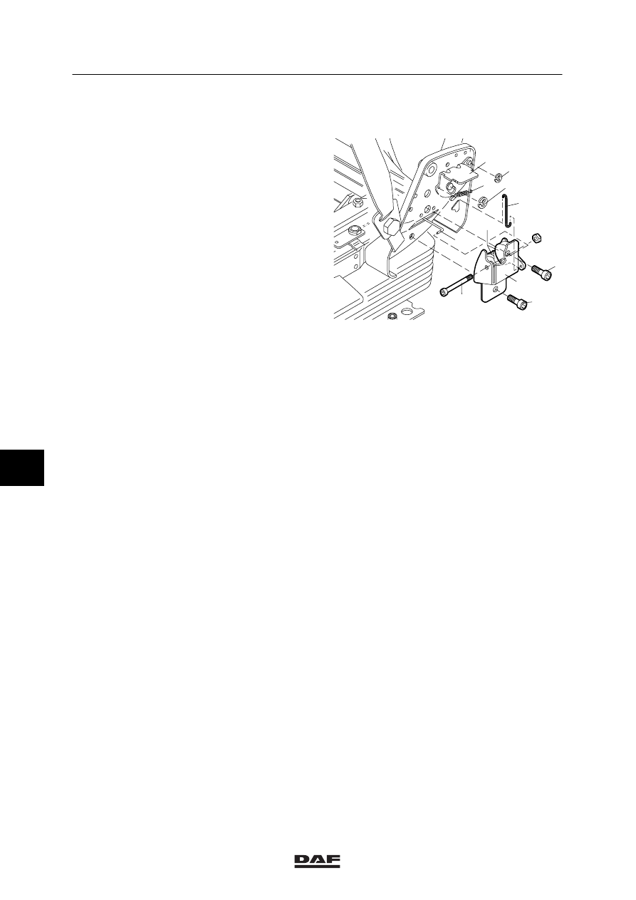
4.24 REMOVAL AND INSTALLATION, BACKREST ADJUSTER

Removing backrest adjuster without
Y-section
1.

Remove the seat squab.

2.

Remove the side cover.

3.

Fold the backrest forward until it stops.

4.

Remove the screws (1) and (2) on control
side and on the opposite side.

5.

Remove the lock rings (3) and (11).

6.

Lift the spring (6) and pull the control plate
(4) from the axle, after which the rod (5) can
be removed.

7.

Loosen the screw (7) of the backrest
adjuster and remove it.

8.

Push the tooth segment assembly from the
bracket (9) until the wire (10) can be
removed.

Installing backrest adjuster without Y-section
1.

Fit the adjuster together with the wire (10)
on one side.

2.

Fit the wire (10) into the tooth segment
assembly at the other side.

3.

Insert the screw (7) into the backrest
adjuster.

4.

Lift the spring (6) and fit the control plate (4)
onto the axle, after which the wire (5) can
be fitted.

5.

Connect the lock rings (3) and (11).

6.

Insert the screws (1) and (2) on control side
and on the opposite side.

K100511

4

3

11

6

5

8

10

1

2

9

7

7

ᓻ 0209

1

Removal and installation

SEATS

4-17

Removing backrest adjuster with Y-section
1.

Remove the seat squab.

2.

Remove the lumbar support.

3.

Remove the side cover.

4.

Remove the screws (1) and (2) on control
side and on the opposite side.

5.

Remove the lock rings (3) and (11).

6.

Lift the spring (6) and pull the control plate
(4) from the axle, after which the rod (5) can
be removed.

7.

Loosen the screw (7) of the backrest
adjuster and remove it.

8.

Loosen the check nut of the coupling piece
in the centre of the pull rod (10) and divide
the pull rod by loosening the coupling piece.

9.

Push the tooth segment assembly from the
bracket (9) until the pull rod (10) can be
removed.

10. Remove the tooth segment (8) combination

together with the bracket (9) from the seat
in downward direction.

Installing backrest adjuster with Y-section
1.

Fit the adjuster together with the pull rod
(10) on either side of the seat.

2.

Fit the coupling piece of the pull rod (10)
together and tighten the check nut.

3.

Insert the screw (7) into the backrest
adjuster.

4.

Lift the spring (6) and fit the control plate (4)
onto the axle, after which the rod (5) can be
fitted.

5.

Connect the lock rings (3) and (11).

6.

Insert the screws (1) and (2) on control side
and on the opposite side.

7.

Fit the side cover, the backrest and the seat
squab.

K101366

4

3

11

6

10

1

2

9

7

5

8

7

ᓻ 0209

1

SEATS

Removal and installation

4-18

4.25 REMOVAL AND INSTALLATION, IPS VALVE

Removing IPS valve

1.

Remove the seat squab.

2.

Remove the side cover on control side.

3.

Disconnect the air pipes from the IPS
valve (1).

4.

Use a screwdriver to lift the IPS valve (1)
from the cover (2) (the valve may be
damaged slightly in the process).

Installing IPS valve
1.

Fit the IPS valve. When fitting, position the
new valve in such a way that the top (3) can
be hooked in and then be pushed down into
the side cover.

2.

Connect the air pipes to the IPS valve (1).

3.

Install the side cover on control side.

4.

Fit the seat squab.

K100510

2

1

3

4.26 REMOVAL AND INSTALLATION, AIR BELLOWS

Removing air bellows
1.

Remove the entire seat.

2.

Remove the seat squab.

3.

Remove the clamping strip (1) (by
cutting it).

4.

Disconnect the air pipe (2) from the
manifold (3).

5.

Unscrew the screws (4) and (5) to be able
to remove the air bellows including the air
pipe.

Installing air bellows
1.

Install the air bellows (6). In doing so, make
sure that the air bellows is not twisted. If this
is nevertheless the case, loosen screw (4) a
few turns and apply spring action to the
system under pressure; then tighten screw
(4) again while the air bellows is still under
pressure.

2.

Tie the pipes together with a clamping strip.

3.

Fit the seat squab.

4.

Install the entire seat.

K100513

6

4

3

1

5

2

7

ᓻ 0209

1

Removal and installation

SEATS

4-19

4.27 REMOVAL AND INSTALLATION, ADJUSTMENT CYLINDER

Removing adjustment cylinder
1.

Remove the seat squab.

2.

Lock the seat in its highest position.

3.

Disconnect the air pipes (1) and (3) from the
adjustment cylinder.

4.

Remove the retainer pin (4).

5.

Remove the screw (5).

6.

Push the metal plates that hold the cylinder
apart and remove the adjustment cylinder.

Installing adjustment cylinder
1.

Push the metal plates that hold the cylinder
apart and insert the adjustment cylinder (2).

2.

Install the retainer pin (4).

3.

Connect the air pipes (1) and (3) to the
adjustment cylinder.

4.

Tighten the screw (5) slightly during
installation.

5.

Release the lock and operate the height
adjustment button (upwards). Check
whether the cylinder (2) moves freely. If not,
loosen screw (5) slightly.

6.

Fit the seat squab.

K100514

4

8

12

6

5

2 1

3

7

ᓻ 0209


Content   ..  853  854  855  856   ..