DAF 95XF. Manual - part 399


  Index      DAF     DAF 95XF Series - service repair manual


Search            


Content   ..  397  398  399  400   ..


DAF 95XF. Manual - part 399


4

XF ENGINE INLET AND EXHAUST SYSTEM

Inspection and adjustment

95

XF series

3-2

3.2

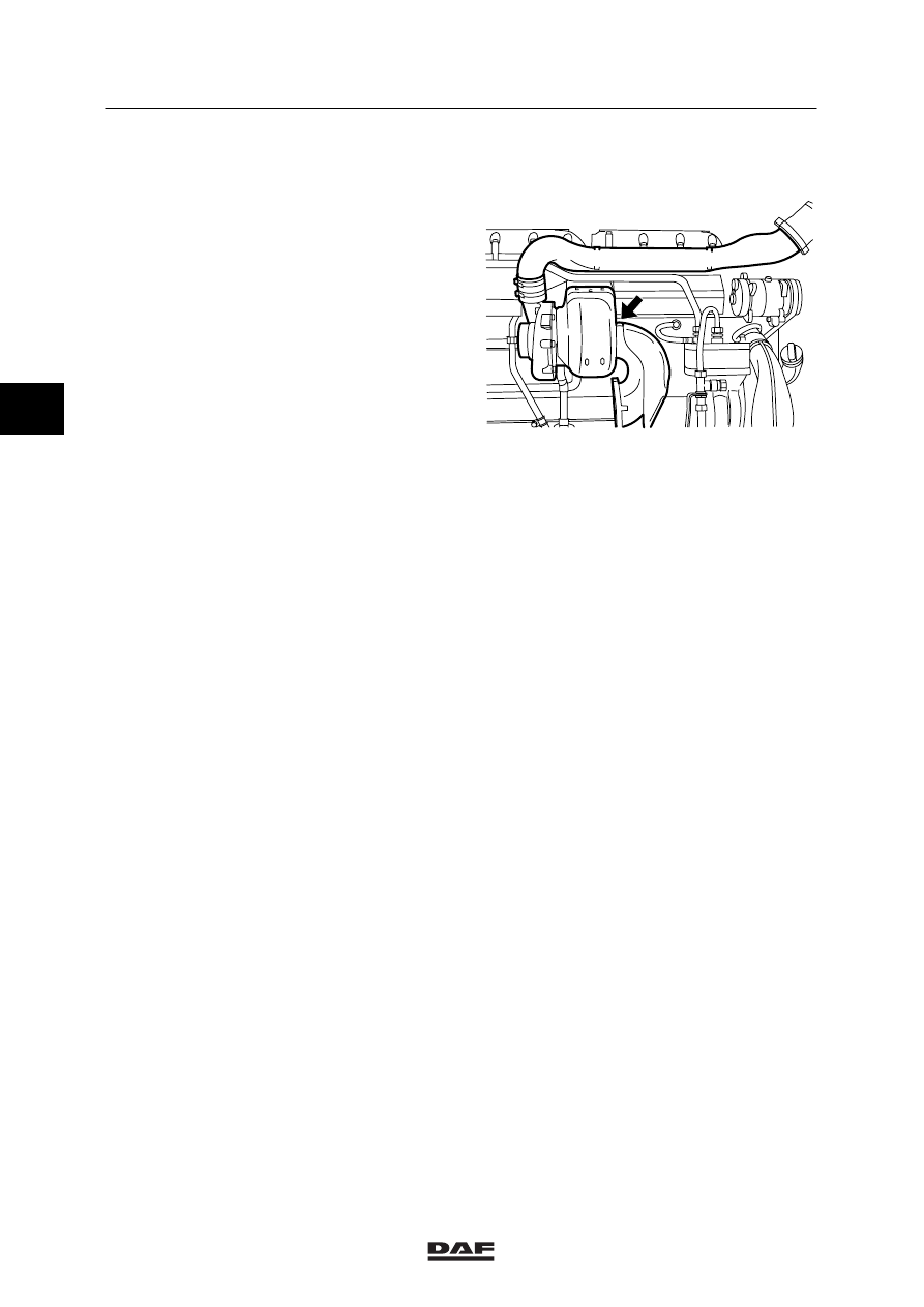
INSPECTION OF EXHAUST BACK PRESSURE

Inspecting the exhaust back pressure
1.

Remove the plug from the exhaust bend
and install a suitable coupling with a pipe.
The first part of the pipe must be made of
metal, to withstand the high temperatures.

2.

Note:
Use an attenuated gauge to prevent
excessive shaking of the gauge needle.

Connect a pressure gauge to the pipe,
with a range of at least 0.1 - 0.2 bar
(10 - 20 kPa).

3.

Note:
The engine brake must not be used during
measurements.
This is done to protect the pressure gauge.

Measure the exhaust back pressure at the
maximum loaded engine speed and
compare the measurement result with the
specified value. See main group “Technical
data”.

i 400180

3

©

 0008

4

95

XF series

Inspection and adjustment

XF ENGINE INLET AND EXHAUST SYSTEM

3-3

3.3

INSPECTION AND PRESSURE-TESTING OF AIR INLET SYSTEM

When pressure-testing the air-inlet
system, the plugs may spring off if
they are not properly secured.

In the air inlet system, check the condition and
attachment of the air inlet channels/ flexible
pipes.

In case of doubt as to the proper sealing of the
air inlet system, indicated by the following:
-

loss of power

-

high fuel consumption

-

unusual noises,

carry out a pressure test to check the air inlet
system for leaks.

1.

Remove the front engine encapsulation.

2.

Remove the air inlet hose between the
intercooler and the inlet manifold.

3.

Install the inlet hose with the special tool
(DAF no. 0694831) on the intercooler,
twisting it slightly.

4.

Remove the air inlet pipe between the air
cleaner housing and the turbocharger intake
port.

5.

Install the special tools (DAF no. 1329310
and DAF no. 1329311) on the turbocharger
intake port.

6.

Connect an air hose with reducing valve to
the plug (A), and charge the system to
approx. 1 bar.

7.

Use soapy water to check the complete inlet
system for air leakage. Also check whether
the pressure gauge of the reducer valve
moves down.

8.

Remove the special tool.

9.

Install the air inlet pipe between the air
cleaner housing and the turbocharger intake
port.

10. Install the inlet hose between intercooler

and inlet manifold and tighten the hose clip
to the specified torque, see main group
“Technical data”.

i 400203

i 400204

A

3

©

 0008

4

XF ENGINE INLET AND EXHAUST SYSTEM

Inspection and adjustment

95

XF series

3-4

3.4

INSPECTION OF INLET UNDERPRESSURE

1.

Remove the connection of the
underpressure sensor from the inlet pipe
between the air cleaner housing and the
turbocharger.

2.

Connect a pressure gauge with a maximum
rating of –100 mbar (–10 kPa) to the
connection of the underpressure sensor.

3.

Measure the inlet underpressure at the
maximum loaded engine speed and
compare the measurement result with the
specified value. See main group “Technical
data”.

i400377

A

3.5

 INSPECTION OF BOOST PRESSURE

To obtain a better indication of where the
problem is, the injection pump gallery pressure,
the inlet underpressure and the exhaust back
pressure can be measured at the same time as
the boost pressure.

Drive the same route each time to obtain as
good a picture as possible.

Turbocharger with wastegate
When you measure the boost pressure curve of
a vehicle fitted with a turbocharger with
wastegate, the air hose between the
compression housing and the diaphragm must
not be disconnected.
The boost pressures measured in a vehicle
fitted with a turbocharger with wastegate are
reliable up to an engine speed of 1500 rpm.
Above this engine speed, the wastegate cuts in
and corrects the boost pressure.

i 400197

3

©

 0008

4

95

XF series

Inspection and adjustment

XF ENGINE INLET AND EXHAUST SYSTEM

3-5

1.

Use a banjo bolt (DAF no. 0664827) to
connect a pressure gauge to the smoke
limiter of the fuel pump, or to the inlet
manifold.

Note:
Preferably use a pressure gauge with a
range of at least 3 bar and a scale division
of 0.1 bar.

2.

The weight of the vehicle should
approximate the maximum combination
weight.

3.

Run the engine at operating temperature
(drive for at least 15 minutes with a loaded
vehicle).

4.

Select the highest gear but one.

5.

In this gear, apply full throttle from 800 rpm.

6.

Note, from 900 rpm, the boost pressure per
100 rpm.

7.

Perform this measurement at least three
times and take the mean values.

8.

Plot a graph on the test sheet with the mean
values found.

Note:
The shape of the curve is important. The
exact value is of less importance.

3

©

 0008


Content   ..  397  398  399  400   ..