DAF 95XF. Manual - part 340
5
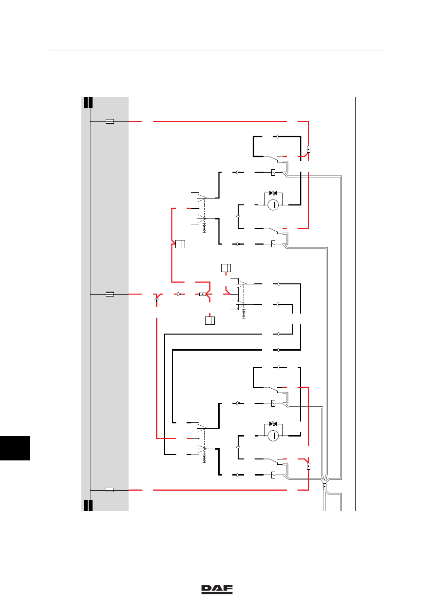
MODIFICATIONS TO THE ELECTRICAL INSTALLATION
Modifications to the electrical installation from chassis number 0E473500
3-46
36
1316630/13-23
EL000252
54
55
56
57
58
59
60
61
62
63
64
65
66
67
68
69
70
71
72
73
74
75
76
77
78
79
80
81
82
83
84
85
86
87
88
89
90
91
92
93
94
96
96
97
98
99
100
101
102
103
104
105
106
26/400
2
276
1208
1208
2
196
1208
1208
C695
4
18
1208
4521
4520
C696
4
18
1208
4523
6
276
4523
4
196
3
196
4520
4
276
4521
3
276
4520
4521
1208
1208
4521
4520
1208
8
276
4525
7
276
17/401
1207
1207
4522
5
276
4522
4524
4524
4525
4527
6
196
4527
1208
8
196
4525
7
196
1233
1233
4526
5
196
4526
4528
4528
4529
35/401
1233
1233
1233
1207
1207
1207
4525
C746
1
18
C774
2
53
4
1
C743
2
53
4
1
G029
30
85
86
87A
87
G028
30
85
86
87A
8
7
M
2
1
B004
C745
2
53
4
1
G031
30
85
86
87A
87
G030
30
85
86
87A
8
7
M
2
1
B003
D878
1010
1000
1010
1000
E044
10A
E033
15A
E034
15A
11
ǹ 0209