DAF 95XF. Manual - part 251


  Index      DAF     DAF 95XF Series - service repair manual


Search            


Content   ..  249  250  251  252   ..


DAF 95XF. Manual - part 251


5

General location of components

LOCATION OF COMPONENTS

1-7

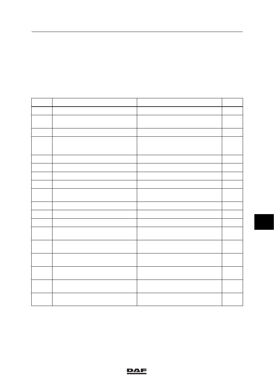
1.2 LOCATION OF COMPONENTS IN RELATION TO THE CIRCUIT DIAGRAM:

1316630/06-12

Column 1

=

Basic code numbers of the
component

Column 2

=

Description

Column 3

=

Location

Column 4

=

Position number in illustration

1

2

3

4

A000

FA (semi-)trailer socket, 7-pin

Rear end of the chassis

32

A001

Rear fog light back-up light socket, FA
(semi-)trailer, 7-pin

Rear end of the chassis

40

A002

FT (semi-)trailer socket, 7-pin

Cab rear

41

A003

Rear fog light back-up light socket,
central supply for FT (semi-)trailer,
7-pin

Cab rear

42

A004

ABS FA (semi-)trailer socket, 7–pin

Rear end of the chassis

43

A005

ABS FT (semi-)trailer socket, 7–pin

Cab rear

44

A021

Connector, diagnostic

Central box, left-hand side

47

A026

Body builder side-light

In chassis, rear left

50

A038

Accessory socket, 2-pin

Behind the bulkhead on the
co-driver’s side

48

A040

Connector, alarm system

Central box, right-hand side

49

A042

Dashboard socket, 2-pin

Front of heating unit, right-hand side

45

A043

Socket, 2-pin

Chair console on driver’s side

46

B036

Resistor, alternator, D+

On print track of printed circuit, central
box.

19

D525

24V/12V Converter

On fixing plate along printed circuit,
central box.

35

D550

CTE–2

On fixing plate under printed circuit,
central box.

7

D587

Electronic unit for ZF intarder

On fixing plate along printed circuit,
central box.

12

D591

Electronic unit for E-gas 3

On fixing plate under printed circuit,
central box.

16

D597

Electronic unit for ASL-V

On fixing plate under printed circuit,
central box.

16

8

ǹ 0009

5

LOCATION OF COMPONENTS

General location of components

1-8

1

2

3

4

D609

Diode for light switch

On print track of printed circuit, central
box.

19

D610

Diode for main beam/dipped beam

On print track of printed circuit, central
box.

19

D611

Diode for lifting gear lowering valve
damping

In lifting gear distributor box

34

D612

Diode for lifting gear lifting valve
damping

In lifting gear distributor box

34

D613

Diode in lifting gear for pump damping
relay

In lifting gear distributor box

34

D622

Diode for lifting gear lifting lock

In lifting gear distributor box

22

D623

Diode for lifting gear lowering lock

In lifting gear distributor box

22

D668

Diode for generator safety D+

On print track of printed circuit, central
box.

19

D703

Diode for switching off the auxiliary
heating/door contact at driver’s side

In diode block, upper console

18

D704

Diode for switching off the auxiliary
heating/door contact at co-driver’s
side

In diode block, upper console

18

D705

Diode for switching off the auxiliary
heating with running engine

In diode block, upper console

18

D708

Diode for interior lighting, prevent
feedback to co-driver’s stepwell

In diode block, upper console

18

D709

Diode for interior lighting, prevent
feedback to co-driver’s switch

In diode block, upper console

18

D710

Diode for interior lighting, prevent
feedback to driver’s switch

In diode block, upper console

18

D721

Diode for parking brake, prevent
feedback

On print track of printed circuit, central
box.

23

D722

Diode for brake lights, prevent
feedback

On print track of printed circuit, central
box.

24

D745

Diode for engine brake (DEB) valves

On print track of printed circuit, central
box.

24

D758

Diode prevent feedback to CWS-2

On print track of printed circuit, central
box.

24

D759

Diode prevent feedback to brake
lights

On print track of printed circuit, central
box.

24

8

ǹ 0009

5

General location of components

LOCATION OF COMPONENTS

1-9

1

2

3

4

D802

Electronic unit for ECAS-2 (6x2)

On fixing plate under printed circuit,
central box.

8

D804

Electronic unit for DAF/Cummins
interface

On fixing plate under printed circuit,
central box.

16

D806

Electronic unit for AGS

On fixing plate along printed circuit,
central box.

9

D809

Electronic unit for ASL-G

On fixing plate under printed circuit,
central box.

16

D813

Electronic unit for gate safety

On fixing plate under printed circuit,
central box.

33

D833

Electronic unit for alarm system

On fixing plate under printed circuit,
central box.

39

D850

Electronic unit for ABS/ASR-D

On fixing plate along printed circuit,
central box.

15

D851

Electronic unit for ECAS-2 (4x2)

On fixing plate under printed circuit,
central box.

8

D853

CWS–2

Behind DIP-3

31

D862

Electronic unit for central door locking

On fixing plate under printed circuit,
central box.

37

D869

Electronic unit for auxiliary heating,
Thermo 90

On fixing plate under printed circuit,
central box.

38

D870

Electronic unit for Voith retarder

On fixing plate under printed circuit,
central box.

12

E112

Fuse for glow indicator lamp

At pre-glow relay

25

E168

Fuse (40A) accessories

At top of printed circuit, central box.

11

E511

Brake light control switch

Left-hand side of heater unit

5

E564

Engine brake control switch

On floor at driver’s side

27

E570

Control switch for coupling/PTO N/10

Above clutch pedal

28

E575

Clutch pedal proximity switch

Above clutch pedal

26

F000

Parking brake control switch

Left-hand side of heater unit

3

F050

Control switch for differential lock
pressure (1st and 2nd diff.)

FT: front of differential housing
FA: in chassis side member

17

F585

Sensor for engine coolant level

Back of header tank

20

G015

Contact relay

Along printed circuit, central box

10

G065

Heater fan relay

Right-hand side of heater unit

6

8

ǹ 0009

5

LOCATION OF COMPONENTS

General location of components

1-10

1

2

3

4

G066

Lifting-gear takeover relay

In lifting gear distributor box

29

G170

Thermo 90 auxiliary heating fan relay

At top of printed circuit, central box.

21

G203

Starting-motor takeover relay

On starting motor

36

G239

Engine brake takeover relay
ABS/ASR-D CTE

Along printed circuit, central box

14

G247

Thermo 90 auxiliary heating fan relay

At top of printed circuit, central box.

21

G257
G258

Recirculation valve microrelay

Right-hand side of heater unit

1

G259

N-10-PTO control relay

Along printed circuit, on right-hand
side, central box

13

G267

Air-conditioning microrelay

Right-hand side of heater unit

2

G279

Heater fan transfer microrelay

Right-hand side of heater unit

4

G284

Microrelay for Voith retarder 133-2

At top of printed circuit, central box.

53

G297

Cab air suspension relay

Along printed circuit, on right-hand
side, central box

54

G300

Thermo 90 auxiliary heating transfer
microrelay (GGVS)

At top of printed circuit, central box.

52

G301

Microrelay, light D+

At top of printed circuit, central box.

55

G302

Microrelay for Swedish lighting

At top of printed circuit, central box.

56

G303

Starting motor lock relay

At top of printed circuit, central box.

51

G723

Connection for central door locking

In the central box

30

8

ǹ 0009


Content   ..  249  250  251  252   ..